Sign In
Upload
Download
Table of Contents
Contents
Add to my manuals
Delete from my manuals
Share
URL of this page:
HTML Link:
Bookmark this page
Add
Manual will be automatically added to "My Manuals"
Print this page
×
Bookmark added
×
Added to my manuals
Manuals
Brands
Lynx Manuals
Speaker System
CLS-212
User manual
Lynx CLS-212 User Manual
Hide thumbs
1
2
Table Of Contents
3
4
5
6
7
8
9
10
11
12
13
14
15
16
17
18
19
20
21
22
23
24
25
26
27
28
29
30
31
32
33
34
35
36
37
38
39
40
41
42
43
44
45
page
of
45
Go
/
45
Contents
Table of Contents
Bookmarks
Table of Contents
Table of Contents
System Overview
Cls-212
Cls-121S
Cls-218S
Back Panel
Connectors and Connections
Fir Filters
Configuring the Dsp Options
Configuration Panel
Online Control System
Hardware and Accessories
Cls-212 Rigging Hardware
Cls-212 How to Fix Cabinets
How to Use the Flying Frame on Cls-212
How to Use the Flying Frame on Cls-212S
Advertisement
Quick Links
Download this manual
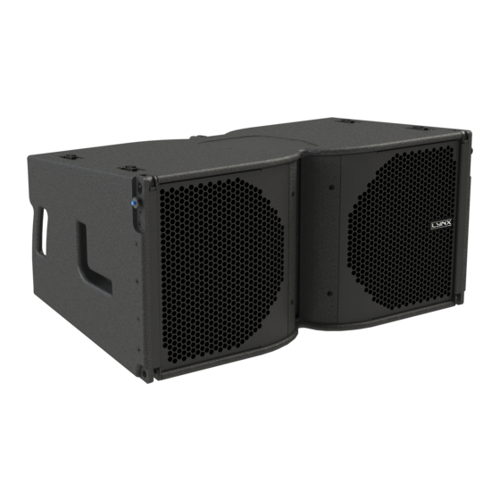
CLS-212
USER MANUAL
CLS-121S
CLS-218S
Lynx Pro Audio S.L.
Valencia, Spain - www.lynxproaudio.com - info@lynxproaudio.com
V.21.01
Table of
Contents
Previous
Page
Next
Page
1
2
3
4
5
Advertisement
Table of Contents
Need help?
Do you have a question about the CLS-212 and is the answer not in the manual?
Ask a question
Questions and answers
Related Manuals for Lynx CLS-212
Speaker System Lynx CLS-218S User Manual
(45 pages)
Speaker System Lynx CLS-28 User Manual
(42 pages)
Speaker System Lynx GXR-LA10A User Manual
(27 pages)
Speaker System Lynx LX-215S User Manual
(20 pages)
Speaker System Lynx ADP-215 User Manual
Adp-215 class d powered (bi-amplified) (21 pages)
Speaker System Lynx LX-V12 User Manual
(37 pages)
Speaker System Lynx LX-F6 User Manual
(43 pages)
Speaker System Lynx ADP Series User Manual
(15 pages)
Speaker System Lynx ionic-100 Quick User Manual
(9 pages)
Speaker System Lynx LX-318C User Manual
Powered cabinet (23 pages)
Speaker System Lynx GXR-12 User Manual
High output, self powered (class d switch mode power supply with pfc), two-way cabinet (12 pages)
Speaker System Lynx ionic-100 Quick User Manual
(8 pages)
This manual is also suitable for:
Cls-121s
Cls-218s
Table of Contents
Print
Rename the bookmark
Delete bookmark?
Delete from my manuals?
Login
Sign In
OR
Sign in with Facebook
Sign in with Google
Upload manual
Upload from disk
Upload from URL


Need help?
Do you have a question about the CLS-212 and is the answer not in the manual?
Questions and answers