Table of Contents
Advertisement
Quick Links
LUXOMAT
Installation and Operating Instruction for B.E.G. - Occupancy detector PD2-M-DALI/DSI-SM/FC
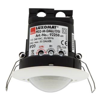
1. Product information
•
Occupancy sensor for daylight-dependent lighting control
•
DALI / DSI interface for controlling digitally dimmable
electronic ballasts as a group
•
Switching between DSI and DALI program by remote
control or DIP switches
•
Version as Master
•
Extension of the coverage area by slave devices are
possible
•
Other functions can be adjustable by remote control.
•
Manual switching and dimming via pushbutton
possible
•
Orientation light function
2. Operation
The presence detector controls the light automatically according
to people present (movements) and the ambient brightness.
The integrated light sensor constantly measures the ambient light
and compares it with the brightness level on the detector. If the
ambient light is sufficient, lighting will not be switched..
If the ambient light level is below the brightness level, a move-
ment activated the lighting in the room.
The detector switch the light off, if there is enough natural light for
5 min. or until the follow-up time do not recognized any move-
ment in the room.
3. Safety information
Work on the 230 V mains supply may only be
carried out by qualified professionals or by
!
instructed persons under the direction and super-
vision of qualified skilled electrical personnel in
accordance with electrotechnical regulations.
Disconnect supply before installing!
This device is not suitable for disconnection.
Mounting the cover cap, after introduction of the
power
4a. Mounting SM
close
open
The detector must be mounted on a flatsolid surface. Before
mounting the detector, the lens must be removed. The circu-
lar cover ring must be removed prior to assembly. To do this,
twist the circular cover ring of the PD2 anticlockwise through
approximately 5° and lift off.
Having connected up the wires in accordance with regula-
tions, put on the cover ring by turning in a clockwise direc-
tion. Apply mains voltage.
4b. Mounting FC
68 mm
A circular opening of diameter 68 mm must be produced in the
ceiling. Having connected up the cables in accor dance with
regulations, the detector is inserted into the opening as shown in
the drawing opposite and fixed into position with the assistance of
the spring clips.
In Master-/Slave-operation the master device must
!
always be installed at location with least daylight.
PD2-M-DALI/DSI / PD2-S
®
5a. Position DIP-Switches, LEDs and
Potentiometer SM
Light measurement
C
B
1
A
2
PD2-
DIP
Surface
3
mounting
5b. Position DIP-Switches, LEDs and
Potentiometer FC
I
II III
A
B
C
Light
measurement
PD2-
False ceiling
mounting
6. Self test cycle/Startup behavior
The product enters an initial 60-second self-test cycle, when the
supply is first connected. During this time the device does not
respond to movement and stays on. (INI-ON or INI-OFF)
The initialization mode can be changed by using the remote control
7. Putting into operation / Settings
TIME
TIME
18 16
10
6
22
18 16
Follow-up time for light control
TIME
10
3
6
25
22
1
3
The time can be set infinitely variably between
25
30
TE
1
18 16
30
10
TE
1 and 30 minutes.
6
22
3
25
1
Symbol TEST: Test mode
30
TE
Every movement switches on the light for a period of 1
second, switching it off for a period of 2 seconds.
LUX
Twilight-switch for light control (relay 1)
2000
LUX
1200
2000
The switch-on value for the light can be set at between
1200
600
200
10 and 2000 Lux. Using the rotary control, the lumi-
600
LUX
2000
200
40
1200
nance set points can be set as desired.
40
600
200
Symbol
: Night-time operation
40
Symbol
: Daytime operation
20%
Orientation lighting
20%
The orientation lighting can be set infinitely variably at
50 30
10
5
60
50 30
20%
10
between 5 and 60 minutes resp. "ON" for permanent
5
60
orientation lighting or "OFF" for no orientation lighting.
50 30
10
5
60
"ON" for permanent orientation lighting
"OFF" deactiviation of orientation lighting.
Pulse spacing PD-Slave
2 or 9 seconds can be set for the pause between 2
9s
2s
9s
2s
pulses sent to the master. The setting can be made with
9s
2s
activated (
) or deactivated ( ) LED indicator.
LED ON
9s
2s
LED ON
For devices with a separate slave input, 2 sec.
LED OFF
LED ON
LED OFF
can be set.
LED OFF
LED ON
LED OFF
DIP-switch function
DIP 1
DIP 2
DIP 3
I II III
Potentiometer A Brightness constant light control
Potentiometer B Off delay for light
Potentiometer C Orientation lighting
LED I green
LED II red
LED III white
L
N
3
1
2
DIP
8. Wiring diagram
Standard mode with Master/Slave
L
N
Connected slaves must have the same phase
as the Master.
9. Manual switching and dimming
By pressing the push button, the phase can be given to the S
terminal.
To turn on or off, press the push button briefly. The light will
remain on or off, as people are detected plus the follow-up time.
With a long key press the light will dimmed manually. When
you release the button, the current brightness value is retained.
With renewed dimming, the dimming direction is reversed.
Fully automatic mode
Semi automatic mode
(VA)
(HA)
LED ON
LED OFF
operation mode DALI
operation mode DSI
L
N
E1 DALI/DSI
DA
DA
T1
S
N
L
+
-
R
DALI
Master
L
N
E1 DALI/DSI
DA
DA
T1
S
N
L
+
-
R
DALI
Master
EN
R
N
L
Slave
R
N
L
Slave
Advertisement
Table of Contents

Subscribe to Our Youtube Channel
Related Manuals for B.E.G. LUXOMAT PD2-M-DALI/DSI-SM/FC


Summary of Contents for B.E.G. LUXOMAT PD2-M-DALI/DSI-SM/FC
- Page 1 LUXOMAT PD2-M-DALI/DSI / PD2-S ® Installation and Operating Instruction for B.E.G. - Occupancy detector PD2-M-DALI/DSI-SM/FC 1. Product information 5a. Position DIP-Switches, LEDs and Potentiometer SM • Occupancy sensor for daylight-dependent lighting control DIP-switch function • DALI / DSI interface for controlling digitally dimmable DIP 1 Fully automatic mode Semi automatic mode...
- Page 2 10. Range 14. LED-functional indicators LED-functional indicators 2,50 m Process Standard mode Double-locked Initialisation time Red flashes Green flashes unprogrammed Initialisation time Red flashes Green flashes programmed quickly quickly Red flashes on Green flashes Motion detection each detected on each detec- movement ted movement Red flashes 2x...
- Page 3 15. Putting into operation of the remote control 21. 100h Function IR-PD-DALI(optional) (long press when closed) Settings with remote control override the potentiometer Exit programming mode T5 and T8 are recommended to burn-in for 100 h at maximum and DIP settings. If there is no entry brightness before dimming.
Need help?
Do you have a question about the LUXOMAT PD2-M-DALI/DSI-SM/FC and is the answer not in the manual?
Questions and answers