Table of Contents
Advertisement
Quick Links
MAINTENANCE &
TROUBLESHOOTING
MANUAL
SERIAL NO.
PS-1030
PS-1430
PS-1930
PRO
SERIES
INFORMATION
To view machine specific information on your
mobile device, scan the code to the left.
Decals with this code can also be found on the
manual box and base of the machine.
DE1316
BY CUSTO M EQUIPMENT LLC
PRO
SERIES
MOBILE
ELEVATING
WORK
PLATFORMS
ANSI A92.20
CSA B354.6:17
PS5.0-M | REV B
Advertisement
Table of Contents

Related Manuals for Custom Equipment HY-BRID LIFTS PRO PS-1030


Summary of Contents for Custom Equipment HY-BRID LIFTS PRO PS-1030
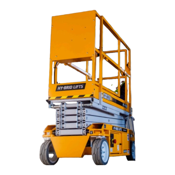
- Page 1 BY CUSTO M EQUIPMENT LLC MAINTENANCE & TROUBLESHOOTING MANUAL SERIAL NO. PS-1030 PS-1430 PS-1930 SERIES MOBILE ELEVATING WORK PLATFORMS SERIES INFORMATION ANSI A92.20 To view machine specific information on your CSA B354.6:17 mobile device, scan the code to the left. Decals with this code can also be found on the PS5.0-M | REV B manual box and base of the machine.
- Page 2 This manual refers to serial number(s): PS-1030 PS10-50001 - PS-1430 PS14-50001 - PS-1930 PS19-50001 - For older Serial Numbers refer to our website: www.hybridlifts.com/Manuals.htm Register your Hy-Brid Lift at: www.hybridlifts.com/RegisterOnline.htm to receive product updates and service bulletins. General Information Register your Hy-Brid Lift at: www.hybridlifts.com/RegisterOnline.htm 2647 Hwy 175 Richfield, WI 53076...
-
Page 3: Forward
The operation and safety manual is considered a part of the work platform and contains instructions and operating procedures essential to properly and safely operate the Custom Equipment Hy-Brid Lift. Users must read and understand all information in the Safety and Operations Manual before operation. -
Page 4: Table Of Contents
TABLE OF CONTENTS FORWARD ....................................3 TABLE OF CONTENTS ................................4 SECTION 1 SAFETY ..................................6 1.1 | SAFETY SYMBOLS ..................................6 1.2 | GENERAL RULES AND PRECAUTIONS ........................... 6 1.3 | SAFETY GUIDELINES ..................................7 SECTION 2 MAINTENANCE ..............................8 2.1 | BATTERY MAINTENANCE ................................8 2.2 | CHARGING THE BATTERY ................................. - Page 5 TABLE OF CONTENTS INDEX OF FIGURES FIGURE 1: Maintenance Lock Use ................................. 7 FIGURE 2: Maintenance Lock Storage ..............................7 FIGURE 3: Battery Location ..................................8 FIGURE 4: Charger Cord Location ................................8 FIGURE 5: Battery Charger LED Display ...............................9 FIGURE 6: LED Light Diagnostic Location ............................20 FIGURE 7: EZ Cal Handheld Controller .............................
-
Page 6: Section 1 Safety
Although Custom Equipment, LLC conforms to specified ANSI, OSHA and CSA, it is the responsibility of the owner to instruct operators with the safety requirements made not only by Custom Equipment, LLC, but by the various safety boards in your area, as well as additional requirements set forth by ANSI, OSHA or CSA. -
Page 7: Safety Guidelines
SECTION 1 SAFETY 1.3 | SAFETY GUIDELINES Maintenance Lock The maintenance lock must be placed into position whenever the machine is being serviced in the raised or partially raised position. Serious injury and/or death could result if maintenance lock is not used properly. FIGURE 1: Maintenance Lock Use FIGURE 2: Maintenance Lock Storage FAILURE TO COMPLY WITH THE LISTED SAFETY... -
Page 8: Section 2 Maintenance
SECTION 2 MAINTENANCE 2.1 | BATTERY MAINTENANCE This unit is equipped with deep cycle 12-volt batteries. The care and maintenance of your batteries has much to do with how well this unit functions. Battery wiring and water level should be checked monthly. -
Page 9: Figure 5: Battery Charger Led Display
SECTION 2 MAINTENANCE BATTERIES GENERATE EXPLOSIVE GASES. KEEP SPARKS AND FLAME AWAY FROM BATTERIES. DO NOT SMOKE WHILE CHARGING. DO NOT OPERATE UNIT WHILE CHARGING. DO NOT DISABLE CHARGER INTERLOCK. FIGURE 5: Battery Charger LED Display Battery Charge Display: Pro Charging Systems IS2412 MEANING Standby Mode (Or battery/ connection error) -
Page 10: Lubrication
SECTION 2 MAINTENANCE 2.3 | LUBRICATION Item Specification Frequency of Lubrication Wheels Teflon Spray Quarterly 2.4 | COMPONENTS REQUIRING ADJUSTMENT Under normal use, no components should require adjustment. Contact the manufacturer if adjustments are required. 2.5 | EXAMINATION, REPAIR, REPLACEMENT OF LIMITED LIFE COMPONENTS With proper use, regular battery charging, and regular inspection, there are no limited life components that require routine replacement. - Page 11 THIS PAGE WAS INTENTIONALLY LEFT BLANK MAINTENANCE & TROUBLESHOOTING MANUAL PS5.0-M REV B...
-
Page 12: Section 3 Maintenance Checklists
SECTION 3 MAINTENANCE CHECKLISTS FAILURE TO PERFORM INSPECTIONS AND PREVENTATIVE MAINTENANCE AT RECOMMENDED INTERVALS MAY RESULT IN THE UNIT BEING OPERATED WITH A DEFECT THAT MAY RESULT IN INJURY OR DEATH OF THE OPERATOR. Regular inspection and conscientious maintenance is important to efficient economical operation of this machine. - Page 13 SECTION 3 MAINTENANCE CHECKLISTS PRO SERIES PRE-START INSPECTION CHECKLIST (Print this page for additional inspections) Model: Serial No. Y-Yes/Acceptable N-No/Unacceptable R-Repaired N/A-Not Equipped VISUAL INSPECTIONS There are no loose or missing parts. Check that warning and instructional labels are legible and secure. Ensure that load capacity is clearly marked.
-
Page 14: Pre-Delivery/Annual/Frequent Inspection Checklist
SECTION 3 MAINTENANCE CHECKLISTS 3.2 | PRE-DELIVERY/ANNUAL/FREQUENT INSPECTION CHECKLIST Model: Serial No. • Check each item listed below. • Use proper operating, service, and maintenance manual for specific information and settings • If an item is found to be unacceptable make the necessary repairs and check the “repaired”... - Page 15 SECTION 3 MAINTENANCE CHECKLISTS Y-Yes/Acceptable N-No/Unacceptable R-Repaired N/A-Not Equipped DECALS: Legibile Correct capacity noted Proper placement & quantity. RAILS/EXTENDING PLATFORM: Extends freely Cables in place/secure Locks in stowed position Locks in extended position FUNCTIONS: All functions (Drive,Elevate,Steer) operational (see Pre-Start Inspection for details) Pothole guards deploy when platform elevated Emergency stop breaks circuits Slow speed mode activates just after units pothole bars are deployed...
-
Page 16: Section 4 Technical References
SECTION 4 TECHNICAL REFERENCES 4.1 | HYDRAULIC SCHEMATIC Part No. HS-112-20-501-50 2 GPM PRO SERIES PS-1030 • PS-1430 • PS-1930... - Page 17 THIRD ANGLE PROJECTION SIZE DWG NO. THE INFORMATION CONTAINED IN THIS DRAWING IS HS-112-20-501 THE SOLE PROPERTY OF CUSTOM EQUIPMENT AND IS LOANED IN EXPECTATION THAT IT WILL BE KEPT CONFIDENTIAL. ANY REPRODUCTION IN PART OR SCALE WEIGHT (LBS.) SHEET...
-
Page 18: Electrical Schematic
SECTION 4 TECHNICAL REFERENCES 4.2 | ELECTRICAL SCHEMATIC Part No. WS-112-20-501-50 +BAT 20 AMP STEERING CONTACTOR BEACON ANG SENS 1 ANG SENS 2 PRES SENS 1 4 5 6 1 2 3 10 11 12 10 11 12 13 14 15 H,L, PRO SERIES PS-1030 •... - Page 19 THIRD ANGLE PROJECTION SIZE DWG NO. THE INFORMATION CONTAINED IN THIS DRAWING IS WS-112-20-501 THE SOLE PROPERTY OF CUSTOM EQUIPMENT AND IS LOANED IN EXPECTATION THAT IT WILL BE KEPT CONFIDENTIAL. ANY REPRODUCTION IN PART OR SCALE WEIGHT (LBS.) SHEET...
-
Page 20: Control Board Diagnostic
SECTION 4 TECHNICAL REFERENCES 4.3 | CONTROL BOARD DIAGNOSTIC If a handheld controller (Part no: ELEC-646-5) When using the LED for diagnosis, note that a is available, it will display error codes and their DUAL FLASH code is indicated. The LED will flash description on/off a certain number of times, pause off for a short delay, then flash on/off a second certain... - Page 21 SECTION 4 TECHNICAL REFERENCES LED Code Possible Cause Check P9 wiring. One or more signals showing outputs when all should be off. Check B+ stud connections on controller. Voltage is too high. There is voltage on safe pre-valve supply when there should not be. Controller may need to be replaced.
-
Page 22: Section 5 Wiring Diagrams
SECTION 5 WIRING DIAGRAMS 5.1 | WIRING DIAGRAM Part No. WD-112-20-501-50 L. STEER R. STEER LIMIT LIMIT SWITCH SWITCH 6AWG TS100 / M2- UP VALVE SPADE CONNECTION ACTUATOR 6AWG 10AWG 10AWG 10AWG 10AWG TS100 30 AMP FUSE 12AWG 6AWG SOLENOID 1 LOWER CONTROL HARNESS CONNECTION... - Page 23 THIRD ANGLE PROJECTION SIZE DWG NO. WD-112-20-501 THE INFORMATION CONTAINED IN THIS DRAWING IS THE SOLE PROPERTY OF CUSTOM EQUIPMENT AND IS LOANED IN EXPECTATION THAT IT WILL BE KEPT CONFIDENTIAL. ANY REPRODUCTION IN PART OR SCALE WEIGHT (LBS.) SHEET...
-
Page 24: Machine Harness Wiring Diagram
SECTION 5 WIRING DIAGRAMS 5.2 | MACHINE HARNESS WIRING DIAGRAM Part No. WD-112-20-532-50 P.H. LIMIT DIODE SWITCH CEI PN: ELEC-755 TVS 5.0 KP BRAKE BRAKE ACTUATOR STEER CONTACTOR FWD STEER CONTACTOR REV PRESSURE SENSOR ANGLE SENSOR 1 ANGLE SENSOR 2 HIRSHMAN POSITION 2 HIRSHMAN... - Page 25 THIRD ANGLE PROJECTION SIZE DWG NO. THE INFORMATION CONTAINED IN THIS DRAWING IS WD-112-21-532 THE SOLE PROPERTY OF CUSTOM EQUIPMENT AND IS LOANED IN EXPECTATION THAT IT WILL BE KEPT CONFIDENTIAL. ANY REPRODUCTION IN PART OR SCALE WEIGHT (LBS.) SHEET...
-
Page 26: Lower Control Wiring Diagram
SECTION 5 WIRING DIAGRAMS 5.3 | LOWER CONTROL WIRING DIAGRAM Part No. WD-112-21-505-50 BEACON KEY SWITCH MACHINE HARNESS ROCKER SWITCH 10 11 TS100 P15 TS100 P12 TS100 P9 A, J E, H 4 5 6 10 11 12 10 11 12 13 14 15 PRO SERIES PS-1030 •... - Page 27 THIRD ANGLE PROJECTION SIZE DWG NO. WD-112-21-505 THE INFORMATION CONTAINED IN THIS DRAWING IS THE SOLE PROPERTY OF CUSTOM EQUIPMENT AND IS LOANED IN EXPECTATION THAT IT WILL BE KEPT CONFIDENTIAL. ANY REPRODUCTION IN PART OR SCALE WEIGHT (LBS.) SHEET...
-
Page 28: Upper Control Wiring Diagram
SECTION 5 WIRING DIAGRAMS 5.4 | UPPER CONTROL WIRING DIAGRAM Part No. WD-112-21-506-50 CANBUS JOY STICK NOT USED REFERENCE ONLY CANBUS BOARD W, X, Y PRO SERIES PS-1030 • PS-1430 • PS-1930... - Page 29 THIRD ANGLE PROJECTION SIZE DWG NO. WD-112-21-506 THE INFORMATION CONTAINED IN THIS DRAWING IS THE SOLE PROPERTY OF CUSTOM EQUIPMENT AND IS LOANED IN EXPECTATION THAT IT WILL BE KEPT CONFIDENTIAL. ANY REPRODUCTION IN PART OR SCALE WEIGHT (LBS.) SHEET...
-
Page 30: Section 6 Troubleshooting Flowcharts
SECTION 6 TROUBLESHOOTING FLOWCHARTS Flowchart: Pro Series-Power Troubleshooting Step 1: Main Power 6.1 | MAIN POWER/SAFETY CIRCUIT WARNING See also Main Power & Safety Circuit Any modification on this machine without Wiring Diagram Or Electrical Schematic the express consent of the manufacturer is prohibited. - Page 31 SECTION 6 TROUBLESHOOTING FLOWCHARTS Troubleshooting Flowcharts--General Notes: WARNING Inspect parts for visible damage as they are encountered. Failure to comply with safety precautions After each step, check if problem has been indentified and/or resolved. may result in damage, injury, or death. If so, make the recommended fix or see a referenced document.
-
Page 32: Drive Circuit
SECTION 6 TROUBLESHOOTING FLOWCHARTS Flowchart-Pro Series-Drive Troubleshooting Step 3: Drive 6.2 | DRIVE CIRCUIT Refer to See also Diagnostic Wiring Diagram Schematic Light Codes in Maintenance Manual Does the machine Is there a trouble Are brakes released? drive? code flashing? Yes, but not properly Cycle power off Check... - Page 33 SECTION 6 TROUBLESHOOTING FLOWCHARTS Troubleshooting Flowcharts--General Notes: WARNING Any modification on this machine without Inspect parts for visible damage as they are encountered. the express consent of the manufacturer After each step, check if problem has been indentified and/or resolved. is prohibited.
-
Page 34: Steer Circuit
SECTION 6 TROUBLESHOOTING FLOWCHARTS Flowchart: Pro Series-Steer 6.3 | STEER CIRCUIT WARNING Any modification on this machine without the express consent of the manufacturer is prohibited. Check for power connection. Does machine steer ? No; Drive, elevate and See Hy-Brid Troubleshooting. (drive, elevate, lower OK) lower not operating (Power connections at pump,... - Page 35 SECTION 6 TROUBLESHOOTING FLOWCHARTS WARNING Failure to comply with safety precautions may result in damage, injury, or death. Refer to Maintenance Manual for complete warnings Contact Hy-Brid Lifts for further troubleshooting Replace limit switch and/or readjust. R1 Failure. Replace Relay. R2, R3, or R4 failure.
-
Page 36: Elevate Circuit
SECTION 6 TROUBLESHOOTING FLOWCHARTS 6.4 | ELEVATE CIRCUIT PRO SERIES PS-1030 • PS-1430 • PS-1930... - Page 37 SECTION 6 TROUBLESHOOTING FLOWCHARTS MAINTENANCE & TROUBLESHOOTING MANUAL PS5.0-M REV B...
-
Page 38: Lower Circuit
SECTION 6 TROUBLESHOOTING FLOWCHARTS Flowchart: Pro Series-Lowering Troubleshooting Step 3B: Lowering 6.5 | LOWER CIRCUIT WARNING: Set up for maintenance safety: Refer to Remove load from platform. See also Wiring Diagram Check for overhead obstructions. What does the Diagnostic Platform movement may occur. diagnostic LED Light Codes in Hydraulic Schem... - Page 39 SECTION 6 TROUBLESHOOTING FLOWCHARTS Troubleshooting Flowcharts--General Notes: WARNING Inspect parts for visible damage as they are encountered. Any modification on this machine without After each step, check if problem has been indentified and/or resolved. the express consent of the manufacturer is prohibited.
-
Page 40: Section 7 Parts
SECTION 7 PARTS USE ONLY MANUFACTURER APPROVED REPLACEMENT OF THE FOLLOWING COMPONENTS REPLACEMENT PARTS. USE OF NON-OEM PARTS WILL AFFECT THE STRENGTH, STABILITY, OR SAFETY WILL VOID WARRANTY. FUNCTION OF THE UNIT: BATTERY (ELEC-047-4), HYDRAULIC CYLINDER (112-21-521-50-K), CONTROL BOARD (112-21-526-56-K), AND ALL STRUCTURAL COMPONENTS. - Page 41 SECTION 7 PARTS Description Part Number Notes ALARM, CONTINUOUS ELEC-635-4 BOARD,DRIVE/LIFT PS 10ANSI S5 112-21-526-50-K BOARD,DRIVE/LIFT PS 14ANSI S5 112-21-526-53-K BOARD,DRIVE/LIFT PS 19ANSI S5 112-21-526-56-K BUTTON,PUSH/PULL RED E-STOP ELEC-071-KIT CHARGER,24V ELEC-795 CORD,NEMA 5-15-P/5-15R,24 IN ELEC-639-9 CTL,ASM LWR PS S5, CAN 112-21-505-50 CTL,ASM UPPR, PS S5 112-21-506-50...
-
Page 42: Section 8 Warranty
8.1 | LIMITED WARRANTY Warranty Statement - Two Year Agreement 8.2 | LIMITED WARRANTIES Subject to the terms, conditions and limitations set forth herein, Custom Equipment, LLC (the “Company”) warrants to the first end-user (“Buyer”) that: Limited Product Warranty For a period of 24 months from the date that a new product manufactured by the Company (“Product”) is delivered to the Buyer, the Product will (i) conform to the specifications published by the Company for such Product as of the date of delivery;... -
Page 43: Exclusive Warranty Remedies
SECTION 8 WARRANTY 8.5 | EXCLUSIVE WARRANTY REMEDIES Exclusive Repair or Replace Remedy The Company’s sole obligation and Buyer’s exclusive remedy with respect to any defect in the Product occurring during the warranty periods set forth in Section 8.1 of this Limited Warranty shall be for the Company, at its option, to repair or replace (or have one of its designated authorized dealers repair or replace) the Product or part, component or assembly thereof that contains a defect in materials or workmanship. -
Page 44: Section 9 Inspection & Repair Log
SECTION 9 INSPECTION & REPAIR LOG DATE COMMENTS PRO SERIES PS-1030 • PS-1430 • PS-1930... - Page 45 SECTION 9 INSPECTION & REPAIR LOG DATE COMMENTS MAINTENANCE & TROUBLESHOOTING MANUAL PS5.0-M REV B...
- Page 46 SECTION 9 INSPECTION & REPAIR LOG DATE COMMENTS PRO SERIES PS-1030 • PS-1430 • PS-1930...
- Page 47 SECTION 9 INSPECTION & REPAIR LOG DATE COMMENTS MAINTENANCE & TROUBLESHOOTING MANUAL PS5.0-M REV B...
- Page 48 2647 Highway 175 Richfield, WI 53076 U.S.A. +1.262.644.1300 +1.262.644.1320 hybridlifts.com “Hy-Brid Lifts” is a trademark of Custom Equipment, LLC. These machines comply with ANSI/SIA A92.20 and CSA B354.6:17. Revision Date: November 2020 Printed in the U.S.A. ©2020 Custom Equipment, LLC...
Need help?
Do you have a question about the HY-BRID LIFTS PRO PS-1030 and is the answer not in the manual?
Questions and answers