
Related Manuals for GE BioProcess LPLC


Summary of Contents for GE BioProcess LPLC
- Page 1 GE Healthcare Life Sciences BioProcess™ LPLC and BioProcess™ MPLC Columns Operating Instructions Original instructions...
-
Page 3: Table Of Contents
Connecting a compressed air supply ..................4.4.3 Process connections ......................... Operation ......................Overview of the operation of BioProcess LPLC and MPLC columns ......Priming the column ..........................Slurry preparation and column filling ..................Column packing ............................ Connecting a packed column ...................... -
Page 5: Introduction
Introduction About this chapter This chapter contains important user information, descriptions of safety notices, regula- tory information, intended use of BioProcess LPLC and MPLC columns, and lists of asso- ciated documentation. In this chapter This chapter includes the following sections:... -
Page 6: About This Manual
BioProcess LPLC and MPLC columns in a safe way. Scope of this document This manual is valid for all variants of standard BioProcess LPLC and MPLC columns. General CE-classification information is provided. Specific configuration information for your column can be found in the product-specific documentation package and on the column label. -
Page 7: Important User Information
Always keep the Operating Instructions at hand when op- erating BioProcess LPLC or MPLC columns. Do not operate BioProcess LPLC or MPLC columns in any other way than described in the user documentation. If you do, you may be exposed to hazards that can lead to personal injury, and you may cause damage to the equipment. - Page 8 1 Introduction 1.2 Important user information Prerequisites In order to operate BioProcess LPLC and MPLC columns safely and according to the intended purpose the following prerequisites must be met: • You should be acquainted with the use of bioprocessing equipment and with the handling of biological materials.
- Page 9 1 Introduction 1.2 Important user information Notices NOTICE NOTICE indicates instructions that must be followed to avoid damage to the product or other equipment. LPLC and MPLC Columns Operating Instructions 28-9638-66 AC...
-
Page 10: Regulatory Information
1 Introduction 1.3 Regulatory information Regulatory information Introduction This section lists the directives and standards that are fulfilled by BioProcess LPLC and MPLC columns. Manufacturing information The table below summarizes the required manufacturing information. For further infor- mation, see the EC Declaration Of Conformity document. - Page 11 • used in the same state as it was delivered from GE Healthcare, except for alterations described in the user documentation. Not applicable to all columns. See the EC Declaration of Conformity document.
- Page 12 1.3 Regulatory information Regulatory compliance of connected equipment Any equipment connected to BioProcess LPLC or MPLC columns should meet the safety requirements of EN 61010-1/IEC 61010-1, or relevant harmonized standards. Within EU, connected equipment must be CE marked. LPLC and MPLC Columns Operating Instructions 28-9638-66 AC...
-
Page 13: Associated Documentation
1 Introduction 1.4 Associated documentation Associated documentation Introduction This section describes the documentation associated with BioProcess LPLC and MPLC columns. Column specific documentation In addition to this Operating Instructions manual, the document package supplied with BioProcess LPLC and MPLC columns also includes documentation binders containing detailed specifications and traceability documents. -
Page 14: Safety Instructions
Important WARNING Before installing, operating or maintaining BioProcess LPLC or MPLC columns, all users must read and understand the entire contents of this chapter to become aware of the hazards involved. Failure to do this may cause human injury or death, or damage to the equipment. -
Page 15: Safety Precautions
Always follow these General Precautions to avoid injury when using BioProcess LPLC or MPLC columns. WARNING Do not operate BioProcess LPLC or MPLC columns in any other way than described in the BioProcess LPLC and MPLC column instruction manual. WARNING... - Page 16 Do not use any accessories not supplied or recommended by GE Healthcare. WARNING Do not use a BioProcess LPLC or MPLC column if it is not working properly, nor if it has suffered any damage, for example: • damage caused by dropping the equipment •...
- Page 17 WARNING EXPLOSION HAZARD! EX classification of BioProcess LPLC and MPLC columns is valid only when it is used according to the EX related safety instructions in this and the sub- sequent chapters. The information is suggested best working practice, but shall not take precedence over individual responsibil- ities or local regulations.
- Page 18 WARNING EXPLOSION HAZARD! When a BioProcess LPLC or MPLC column is used in a potentially explosive atmosphere, EX-rated tools, equipment and clothing MUST be used. LPLC and MPLC Columns Operating Instructions 28-9638-66 AC...
- Page 19 BioProcess LPLC or MPLC columns Installation Guide. WARNING EXPLOSION HAZARD! When a BioProcess LPLC or MPLC column is operated or maintained in a potentially explosive atmosphere, it MUST be properly grounded to avoid static discharge.
- Page 20 Personal protection WARNING Always use appropriate personal protective equipment during operation and maintenance of BioProcess LPLC or MPLC columns. LPLC and MPLC Columns Operating Instructions 28-9638-66 AC...
- Page 21 Even if the instructions in the Safety Instructions and User Manual are followed, it is the customers' responsibility to guarantee the safety of the personnel working with BioProcess LPLC or MPLC columns. LPLC and MPLC Columns Operating Instructions 28-9638-66 AC...
- Page 22 CAUTION Installing and moving the equipment involves lifting heavy parts. It is advisable to always have at least two people on hand, as well as a hoist, when moving or lifting BioProcess LPLC or MPLC columns. Operation WARNING Before use, check that the column is not damaged or otherwise defective.
- Page 23 WARNING Operating limits. Never exceed the operating limits stated in this document and on the column label. If BioProcess LPLC or MPLC columns are operated outside these limits, the equipment may be damaged and bodily injury or death may occur.
- Page 24 Maintenance WARNING LOCK OUT / TAG OUT! Before any maintenance or decommission- ing work is performed on BioProcess LPLC or MPLC columns, make sure that: • the column is empty and depressurized. Note that the column can be pressurized even when the system is closed down.
- Page 25 2 Safety instructions 2.1 Safety precautions WARNING There is a risk of injury to your fingers and other appendages if they become trapped between the lid and the column tube. Handle the lid with care. CAUTION Maintenance of the equipment may involve lifting heavy parts. It is advisable to always have at least two people on hand, as well as a hoist, when performing service and maintenance on BioProcess LPLC or MPLC columns.
-
Page 26: Labels
2 Safety instructions 2.2 Labels Labels Introduction This section describes the various labels on BioProcess LPLC and MPLC columns and their meaning. Column label The illustration below shows an example of the identification label found on BioProcess LPLC and MPLC columns. The label shows the specific manufacturing and performance data for individual BioProcess LPLC or MPLC columns. - Page 27 Code No. Number indicating instrument is a BioProcess LPLC or MPLC column product. Serial No. Number of the specific column.
- Page 28 See Section 2.3 Emergency procedures, on page 29 for further information regarding the emergency stop. IMPORTANT! Before service/maintenance or return to GE Healthcare, clean the equipment and accompany it with a decontamination statement, specifying substances with which it has been in contact during use and the method of cleaning.
-
Page 29: Emergency Procedures
2 Safety instructions 2.3 Emergency procedures Emergency procedures Introduction This section describes how to perform an emergency shutdown of BioProcess LPLC and MPLC columns. Precautions WARNING Pressure will remain in the column and piping for an extended pe- riod after shutdown. Make sure all lines and chambers are depres- surized before opening or dissconnecting. -
Page 30: Recycling Information
Disposal: general instructions When taking BioProcess LPLC or MPLC columns out of service, the different materials must be separated and recycled according to national and local environmental regula- tions. -
Page 31: Column Description
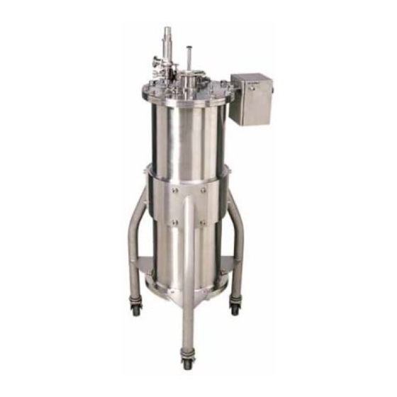
3 Column description Column description About this chapter This chapter provides a description of BioProcess LPLC and MPLC columns and illustrates and describes the main features of columns and column components. Structural components BioProcess LPLC and MPLC columns feature a specially designed flow distribution system fitted at the top and bottom of the column that ensures a uniform distribution of the mobile phase across the whole bed. - Page 32 BioProcess LPLC and MPLC columns The schematic drawing below illustrates the general features of BioProcess LPLC and MPLC columns. The exact configuration may vary from column to column. For specific configuration details, refer to the product documentation package provided with your BioProcess LPLC or MPLC column.
- Page 33 The image below shows a general schematic overview of column control box features. Specific control box configurations may vary from column to column. For column-spe- cific control box configuration details and pneumatic hose connection diameters, please refer to the product documentation package provided with your BioProcess LPLC or MPLC column. PRESSURE...
- Page 34 3 Column description Part Description Function Air supply inlet Inlet connection for compressed air supply. Pressure indicator Manometer display guage. Slurry valve Connection for attachment of pneumatic hose to Port 1 port 1 on the lower slurry valve for closing the valve.
- Page 35 3 Column description Port Description Function Connection point for pneumatic hose Controls the closing of the slurry from column control box valve port 1. valve. Connection point for pneumatic hose Controls the opening of the from column control box valve port 2. slurry valve.
-
Page 36: Installation
4 Installation Installation About this chapter This chapter provides general information required to enable users and service personnel to transport, unpack, move and install BioProcess LPLC and MPLC columns. In this chapter This chapter includes the following sections: Section See page 4.1 Site requirements... - Page 37 Tipping risk. When lifting and moving BioProcess LPLC or MPLC columns, make sure that the fork is inserted under the center of the BioProcess LPLC or MPLC column. The center of gravity of Bio- Process LPLC and MPLC columns is high and the BioProcess LPLC or MPLC column may tip over if the forks are offset too far to either side.
-
Page 38: Site Requirements
Dimensions and weight, on page 94 Note: Make sure that the floor can handle the weight of the BioProcess LPLC or MPLC column at fully loaded conditions. Please observe that for the weight to be equally distributed over all wheels, the floor must be level and without irregu- larities. - Page 39 Media supply must be arranged so that piping dimensions, piping lengths, valves and height differences do not obstruct processing. For specifications regarding media supply and connection requirements, please refer to the EDS in the documentation provided with your BioProcess LPLC or MPLC column. LPLC and MPLC Columns Operating Instructions 28-9638-66 AC...
-
Page 40: Transport
BioProcess LPLC and MPLC columns can be rolled by hand on hard and level surfaces with wheel brakes released. • If the floor quality does not allow rolling of the BioProcess LPLC or MPLC column on its own wheels, it can be moved with a pallet jack or forklift. Note: Make sure that intended openings and apertures are large enough to allow passage of the column. - Page 41 Master Mover coupling (not available on all models) BioProcess LPLC and MPLC columns may be equipped with a Master Mover coupling. A Master Mover can be connected to the Master Mover coupling to assist in manoevering BioProcess LPLC or MPLC columns after unpacking.
-
Page 42: Unpacking Bioprocess Lplc And Mplc Columns
4.3 Unpacking BioProcess LPLC and MPLC columns Unpacking BioProcess LPLC and MPLC columns Introduction This section describes the tools and procedure required to unpack BioProcess LPLC and MPLC columns from the transport box. Tools required for unpacking The following tools are recommended when unpacking BioProcess LPLC and MPLC columns from the transport box: •... - Page 43 4 Installation 4.3 Unpacking BioProcess LPLC and MPLC columns Visual inspection When unpacking BioProcess LPLC and MPLC columns from the transport box check: • if all equipment is enclosed in the transport box according to the packing list. • if there is any apparent damage to the equipment.
-
Page 44: Setup
4 Installation 4.4 Setup Setup Introduction This section describes the steps that need to be taken to set up BioProcess LPLC and MPLC columns before use. In this section Section See page 4.4.1 Assembly of BioProcess LPLC and MPLC columns 4.4.2 Connecting a compressed air supply... -
Page 45: Assembly Of Bioprocess Lplc And Mplc Columns
4 Installation 4.4 Setup 4.4.1 Assembly of BioProcess LPLC and MPLC columns 4.4.1 Assembly of BioProcess LPLC and MPLC columns Introduction This section describes how to level the column and lock the wheels before making further adjustments and process connections. - Page 46 4 Installation 4.4 Setup 4.4.1 Assembly of BioProcess LPLC and MPLC columns Lock the wheels After positioning the column in its operational location, lock the wheels as illustrated below. Levelling the column Before operation the column must be level. Use a spirit level to check if the column is level.
-
Page 47: Connecting A Compressed Air Supply
4 Installation 4.4 Setup 4.4.2 Connecting a compressed air supply 4.4.2 Connecting a compressed air supply Introduction Pneumatic slurry valves are opened and closed using compressed air. This section briefly describes the connection of a compressed air supply to the pneumatic control box. The valve ports of the control box are subsequently connected to the ports of the pneumatic slurry valve, see Chapter 3 Column description, on page 31. -
Page 48: Process Connections
4.4.3 Process connections Introduction This section provides guidelines for hydraulic fluid connections and other process con- nections for setting up BioProcess LPLC and MPLC columns for operation. General guidelines for connections • Use piping or tubing that has an internal diameter sufficient for the flow rate specified. -
Page 49: Operation
5 Operation Operation About this chapter BioProcess LPLC and MPLC columns can be operated using various media. This chapter presents a general overview of procedures for column packing and unpacking. Note: Adaptation of the procedures described in this chapter may be necessary de- pending on factors such as the media used, the intended purpose, the process environment and local regulations. -
Page 50: Overview Of The Operation Of Bioprocess Lplc And Mplc Columns
Overview of the operation of BioProcess LPLC and MPLC columns Introduction This section provides a general overview of the use of BioProcess LPLC and MPLC columns. Principles of operation The operation of BioProcess LPLC and MPLC columns consists of the following steps: •... - Page 51 5 Operation 5.1 Overview of the operation of BioProcess LPLC and MPLC columns The schematic diagram above illustrates the main features and equipment used in priming, packing and unpacking BioProcess LPLC and MPLC columns. Part Description Slurry tank Water/buffer tank...
-
Page 52: Priming The Column
5 Operation 5.2 Priming the column Priming the column Introduction This section describes how to prime the column to remove air from the column and bed supports before the column is packed. Hydraulic chamber priming NOTICE The hydraulic fluid tank must be filled with hydraulic fluid or other bacteriostatic solution before the hydraulic chamber priming pro- cedure is performed. - Page 53 5 Operation 5.2 Priming the column Step Action Start the packing pump and fill the hydraulic chamber with ethanol (20% or higher) or other bacteriostatic solution. When all air has been removed, close the hydraulic inlet and hydraulic outlet and set the pressure relief valve to the desired target pressure. Stop the packing pump and close the hydraulic chamber inlet.
- Page 54 5 Operation 5.2 Priming the column Step Action Open the mobile phase bottom valve (MPB) and close the mobile phase top valve (MPT). Air will then be removed from the bottom bed support. When the air has been removed from the bottom bed support, close the mobile phase bottom valve (MPB) and turn off the filling pump.
-
Page 55: Slurry Preparation And Column Filling
5.3 Slurry preparation and column filling Slurry preparation and column filling Introduction This section describes how to fill BioProcess LPLC and MPLC columns with slurry. Slurry preparation The slurry concentration that can be used for filling the column may be a slurry prepa- ration of between 40% and 70%, dependant on the target bed height and compression factor. - Page 56 5 Operation 5.3 Slurry preparation and column filling Step Action Open the bottom slurry valve (BSV). Open the hydraulic outlet (HO). Open valve (B) and start the filling pump. Slurry is pumped into the column and the adapter moves upwards when hydraulic liquid is pushed out of the hydraulic chamber.
-
Page 57: Column Packing
Introduction This section describes how to pack media slurry in the column after the column and hydraulic chamber have been primed. Packing BioProcess LPLC and MPLC columns with media slurry Tip: It is recommended that column filling is performed immediately prior to the column packing step. - Page 58 WARNING Operating limits. Never exceed the operating limits stated in this document and on the column label. If BioProcess LPLC or MPLC columns are operated outside these limits, the equipment may be damaged and bodily injury or death may occur.
- Page 59 5 Operation 5.4 Column packing NOTICE Refer to the media user manual for expected HETP result information. LPLC and MPLC Columns Operating Instructions 28-9638-66 AC...
-
Page 60: Connecting A Packed Column
Runs are performed in accordance with the standard operating procedures of the cus- tomer. Contact your GE Healthcare representative if you require assistance in developing standard operating procedures for your media. Preparations When a column has been packed and satisfactory HETP test results have been obtained, the column is ready for use. - Page 61 5 Operation 5.5 Connecting a packed column Step Action Using the pump, fill the system with an appropriate liquid for column instal- lation. When the system is filled with liquid, including the tubing connected to the column bottom system valve, connect the other end of the tubing to the bottom of the column.
- Page 62 5 Operation 5.5 Connecting a packed column Final considerations Once the column is connected, the following should be taken into consideration. • Make sure to activate the system alarm(s) again after the filling sequence. • When the pump is started, the system must be in Column UpFlow position. •...
-
Page 63: Unpacking Bioprocess Lplc And Mplc Columns
5 Operation 5.6 Unpacking BioProcess LPLC and MPLC columns Unpacking BioProcess LPLC and MPLC columns Introduction This section describes the procedures used to unpack the column after a run and explains how residual media is removed from the column. Overview of unpacking The hydraulic fluid tank and unpacking buffer/water tank must be connected to the packing pump when unpacking a column. - Page 64 5 Operation 5.6 Unpacking BioProcess LPLC and MPLC columns Loosening the packing bed Step Action Open the hydraulic outlet (HO). Open the mobile phase bottom valve (MPB). Start the packing pump at a flow rate of 50%. The water or unpacking buffer will enter the column through the mobile phase bottom opening.
- Page 65 5 Operation 5.6 Unpacking BioProcess LPLC and MPLC columns Step Action After 1 column volume (CV), close the mobile phase bottom valve (MPB) and change the unpacking buffer inlet to the mobile phase top (MPT) opening. Stop the pump after 0.5 CV. Close the mobile phase top opening and allow the packed bed to loosen for around 2 to 5 minutes.
- Page 66 5 Operation 5.6 Unpacking BioProcess LPLC and MPLC columns Step Action Make sure that the mobile phase top and mobile phase bottom inlets are closed, then connect the packing pump to the hydraulic inlet (HI) and close the hydraulic outlet (HO).
- Page 67 5 Operation 5.6 Unpacking BioProcess LPLC and MPLC columns Step Action Connect the packing pump to the mobile phase bottom valve (MPB). Open the bottom slurry valve. Close the hydraulic chamber inlet and outlets. Close the mobile phase top valve (MPT).
-
Page 68: Maintenance
6.4 Cleaning and storage Precautions WARNING EXPLOSION HAZARD! When a BioProcess LPLC or MPLC column is operated or maintained in a potentially explosive atmosphere, it MUST be properly grounded to avoid static discharge. LPLC and MPLC Columns Operating Instructions 28-9638-66 AC... - Page 69 6 Maintenance WARNING LOCK OUT / TAG OUT! Before any maintenance or decommission- ing work is performed on BioProcess LPLC or MPLC columns, make sure that: • the column is empty and depressurized. Note that the column can be pressurized even when the system is closed down.
- Page 70 6 Maintenance WARNING There is a risk of injury to your fingers or other appendages if they become trapped between an end plate and the column tube. Handle the end plates with care. CAUTION A sudden release of pressure when disconnecting tubing may cause injury.
-
Page 71: Disassembling The Column
6 Maintenance 6.1 Disassembling the column Disassembling the column Introduction This section describes how to disassemble the column before performing maintenance, service or cleaning procedures. Equipment required for disassembly/assembly • Crane or hoist • Forklift or other suitable mechanical lifting equipment for lowering and lifting the bottom end plate •... - Page 72 6 Maintenance 6.1 Disassembling the column Step Action With the part of the adapter outside of the column fully extended: Open the hydraulic chamber valve. Pump in fluid (water or other appropriate buffer) through the bottom mobile phase. Open the top mobile phase valve, with tubing leading to waste.
- Page 73 Removing the bottom end plate The bottom end plate is most easily removed by placing a mechanical lifting device un- derneath the column. Contact your GE Healthcare representative for information about lifting devices suitable for different column types. To remove the bottom end plate:...
-
Page 74: Changing O-Rings And Seals
This section describes how to change column O-rings and seals. Tip: GE Healthcare recommends that column O-rings and seals are changed at least once each year. It may be necessary to change O-rings and seals exposed to some form of movement in the column more frequently, for example the O-rings on the adapter. - Page 75 6 Maintenance 6.2 Changing O-rings and seals Step Action Remove the excluder (A). Use a sharp knife to cut the excluder if necessary. Use a sharp knife to remove the step seal (B) protecting the O-ring. Remove the O-ring by inserting a length of wire (2 mm diameter, approximate length 20 mm) into the groove surrounding the O-ring and picking the O-ring out.
- Page 76 6 Maintenance 6.2 Changing O-rings and seals Step Action Place one edge of the new step seal onto the O-ring in the groove of the packing housing. Make sure the step seal is in the orientation indicated in the cross-section diagram below. Part Description Upper surface of top end plate.
- Page 77 6 Maintenance 6.2 Changing O-rings and seals Top end plate The top end plate has a single O-ring around its inner circumference. To change the O-ring: Step Action Using a sharp knife, cut the existing O-ring (A) and remove it. Mount a new O-ring onto the top end plate.
- Page 78 6 Maintenance 6.2 Changing O-rings and seals Adapter The adapter has two O-rings that are protected by seals. The liquid distributor also has an O-ring and there is a seal protecting the leakage detection system aperture. An addi- tional seal holds the upper bed support in place. To change these: Step Action Remove the seal protecting the leakage detection system aperture.
- Page 79 6 Maintenance 6.2 Changing O-rings and seals Step Action Remove the O-rings and seals and replace these with new O-rings and seals. Tip: Warming the new O-rings and seals in warm water (50°C) will make them more pliable and easier to mount onto the adapter. Replace the seal protecting the leakage detection system aperture with a new seal.
- Page 80 6 Maintenance 6.2 Changing O-rings and seals Step Action Carefully slide the housing cover up over the adapter rod to expose the O-ring (A). Remove the used O-ring, clean the surfaces with 100% ethanol and mount a new O-ring in place. Replace the adapter rod housing cover and bolt into place.
- Page 81 6 Maintenance 6.2 Changing O-rings and seals Bottom end plate and liquid distributor The bottom end plate has an O-ring that is in contact with the column tube. The bottom end plate also houses the liquid distributor and the lower bed support. Both of these have O-rings that must be changed periodically.
- Page 82 6 Maintenance 6.2 Changing O-rings and seals Step Action Remove the lower bed support and bed support O-ring. Part Description Lower bed support. Bed support O-ring groove. Seal groove. Bottom end plate O-ring. Remove the O-ring from the outer circumference of the bottom end plate. LPLC and MPLC Columns Operating Instructions 28-9638-66 AC...
- Page 83 6 Maintenance 6.2 Changing O-rings and seals Step Action Remove the bolts and fittings holding the distributor in place on the lower surface of the bottom end plate. These bolts and distributor fittings are easily removed using a Hex/Allen key. Part Description Liquid distributor.
- Page 84 6 Maintenance 6.2 Changing O-rings and seals Step Action Place the lower bed support on top of the liquid distributor and fix this into place with a new bed support seal. The bed support seal also covers the O-ring in the upper groove of the bottom end plate. Tip: Warming the seal in warm water (50°C) will make it more pliable and easier to mount onto the bottom end plate.
- Page 85 6 Maintenance 6.2 Changing O-rings and seals Step Action Clean the valve and column inlet with 100% ethanol. Lubricate the new O-rings with 20% ethanol and then fit the O-rings into position. Reinsert the valve and fix into position with the TC clamp. LPLC and MPLC Columns Operating Instructions 28-9638-66 AC...
-
Page 86: Assembling The Column
Fitting the bottom end plate The bottom end plate is most easily repositioned during reassembly by placing a mechanical lifting device underneath the column. Contact your GE Healthcare represen- tative for information about lifting devices suitable for different column types. - Page 87 6 Maintenance 6.3 Assembling the column Step Action Tighten the bolts successively, sequentially tightening diagonally opposite pairs of bolts using equal amounts of torque, to raise the bottom end plate into position in the column tube. Carefully lower and remove the lifting device. Replace the bottom mobile phase valve.
- Page 88 6 Maintenance 6.3 Assembling the column Step Action Insert T-shaped jacking bolts into the top end plate and into the column. Successively tighten the bolts by equal amounts to push the adapter and top end plate into the column, lowering the crane/hoist as necessary. Insert the bolts when the adapter and top end plate have entered the column sufficiently.
-
Page 89: Cleaning And Storage
Cleaning of the column should be aimed at prevention rather than cleaning due to growth or contamination. Cleaning exterior surfaces BioProcess LPLC and MPLC columns are designed to be operated in a clean environment. The external surfaces should not normally accumulate any substantial amount of dust or dirt. - Page 90 6 Maintenance 6.4 Cleaning and storage Storage Appropriate storage solutions are determined by the specific chromatography media used in packing the column. Please refer to the Chemical Resistance Chart in Chapter 8 Reference information, on page 94 for information about specific media. Avoid any solution that may compromise the quality of the chromatography media.
-
Page 91: Troubleshooting
BioProcess LPLC and MPLC columns. The following guide presents a series of questions to direct the operator to the cause of the problem. If the problem persists or cannot be resolved using this guide, contact your GE Healthcare representative for advice. High back-pressure •... - Page 92 7 Troubleshooting • Is there media in the buffer return line? Check that the bed support is correctly fas- tened to the adapter/bottom unit. Check the bed support retaining apparatus in the center of the bed support. Chromatograms not as expected •...
- Page 93 7 Troubleshooting Step Action Pump a solution that is a few degrees Celsius warmer than the media upwards through the column. Test the column again before using. LPLC and MPLC Columns Operating Instructions 28-9638-66 AC...
-
Page 94: Reference Information
Horizontal +/- 1° Dimensions and weight Specific dimension and weight information for BioProcess LPLC and MPLC columns is provided in the documentation package supplied with your column. The following table provides examples of the categories of information that can be found in the documen- tation package. - Page 95 Maximum bed height (uncompressed) Minimum height necessary for maintenance Footprint dimensions Total weight Adapter weight Chemical resistance guidelines When using BioProcess LPLC or MPLC columns it is recommended that the following chemicals are avoided: • Extreme oxidizers • Fluorine and halogenated compounds •...
- Page 96 8 Reference information NOTICE Chlorides and low pH can cause corrosion on stainless steel. Rinse thoroughly with clean water after use. Inspect the column regularly for signs of corrosive attacks, which may cause column damage if untreated. Note that the stainless steel bed supports are especially vulnerable to corro- sion.
- Page 97 8 Reference information † Chemical Concen- Time/cycle Comments Operating CAS no. tration restrictions temperature Ethanol 12 months Storage 2°C to 30°C 64-17-5 and max. 0.5 Ethanol 2°C to 30°C 64-17-5 Ethanol/ 20%/ 10% 2°C to 30°C 64-17-5/ acetic acid 64-19-7 Guanidinium 2°C to 30°C 50-01-1...
- Page 98 8 Reference information Footnotes When a concentration is stated as a percentage, this is v/v. † CAS no.: Registration number assigned by the Chemical Abstract Services (CAS), American Chemical Society. ‡ A pH below 4 is not recommended for stainless steel. §...
-
Page 99: Index
Index Index Adapter Filling a column with slurry, 55 Lowering into column, 87 Filling pump, 51 O-rings and seals, 78 Adapter rod O-rings, 79 General connection guide- Air trapped in column, 92 lines, 48 Assembling the column, 86 General technical specifica- tions, 94 Before operation, 7 Bottom end plate... - Page 100 Index Space and floor load, 29 Storage, 90 Reference information, 94 Regulatory information, 10 Top end plate Fitting, 87 Safety labels, 28 Transport, unpacked, 40 Safety notices, 8 Transport in crate, 40 Safety precautions, 14 Typographical conventions, 6 Slurry compression, 55 Slurry preparation, 55 Slurry valve Unpacking instructions, 42...
- Page 102 751 84 Uppsala All goods and services are sold subject to the terms and conditions of sale of the company within GE Healthcare which supplies them. A copy of these terms Sweden and conditions is available on request. Contact your local GE Healthcare repre- sentative for the most current information.
Need help?
Do you have a question about the BioProcess LPLC and is the answer not in the manual?
Questions and answers