Table of Contents
Advertisement
Quick Links
Advertisement
Table of Contents

Related Manuals for FIC FS39


Summary of Contents for FIC FS39
- Page 1 DOC No.: M00B02 Rev. : A0 Date : 12, 2000 Part No. : 25-11604-20...
- Page 2 Table of Contents Table of Contents Chapter 1 Overview Chapter 2 Installation Procedures...
- Page 3 FS39 Mainboard Manual Chapter 3 BIOS Setup Appendix...
- Page 4 Overview Chapter 1 Overview 1 - 1...
- Page 5 FS39 Mainboard Manual Package Checklist The mainboard This user manual One FDD cable One HDD cable One ATA/66 cable Two software CDs (CD Pro, CD Plus) 1 - 2...
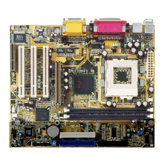
- Page 6 Overview The FS39 Mainboard 1 - 3...
-
Page 7: Main Features
FS39 Mainboard Manual Main Features 1 - 4... - Page 8 Overview 1 - 5...
-
Page 9: Acpi Ready
FS39 Mainboard Manual ACPI Ready FIC Unique Innovation for Users (NOVUS) - Enhanced Mainboard Features and System Support NOTE: 1. LogoGenie supports Award BIOS only. 2. If you create a Logo file (.bmp) by LogoGenie, the file size must ||||be 640 x 464 x 256 colors. - Page 10 Overview WARNING: While excute Step3 below, please do not turn off the sytsem power in order to avoid BIOS damage. NOTE: However, if it is disabled and while boot the system, the POST screen will be held and shows you the message to let you know the current status of BIOS Guardian.
- Page 11 FS39 Mainboard Manual 1 - 8...
-
Page 12: Installation Procedures
Installation Procedures Chapter 2 Installation Procedures WARNING: Excessive torque may damage the mainboard. When using an electric screwdriver on the mainboard, make sure that the torque is set to the allowable range of 5.0 ~ 8.0kg/cm. Mainboard components contain very delicate Integrated Circuit (IC) chips. - Page 13 FS39 Mainboard Manual Quick Reference (from Page 2-2 to 2-3) Mainboard Layout 2 - 2...
- Page 14 Installation Procedures Clear CMOS, Clear Password Front Panel Block Cable Connection CPU Fan Installation 2 - 3...
-
Page 15: Set System Jumpers/Switches
FS39 Mainboard Manual 1). Set System Jumpers/Switches NOTE: Users are not encouraged to change the jumper settings not listed in this manual. Changing the jumper settings improperly may adversely affect system performance. 2 - 4... - Page 16 Installation Procedures 2 - 5...
-
Page 17: Install Memory Modules
FS39 Mainboard Manual 2). Install Memory Modules 2 - 6... -
Page 18: Install The Cpu
Installation Procedures 3). Install the CPU 2 - 7... -
Page 19: Install Expansion Cards
FS39 Mainboard Manual 4). Install Expansion Cards CAUTION: Make sure to unplug the power supply when adding or removing expansion cards or other system components. Failure to do so may cause severe damage to both the mainboard and expansioncards. Always observe static electricity precautions. -
Page 20: Connect Devices
Installation Procedures 5). Connect Devices 2 - 9... - Page 21 FS39 Mainboard Manual 2 - 10...
- Page 22 Installation Procedures 2 - 11...
- Page 23 FS39 Mainboard Manual 2 - 12...
- Page 24 Installation Procedures 2 - 13...
- Page 25 FS39 Mainboard Manual 2 - 14...
- Page 26 Installation Procedures 2 - 15...
- Page 27 FS39 Mainboard Manual 2 - 16...
- Page 28 Installation Procedures 2 - 17...
- Page 29 FS39 Mainboard Manual This Page Left Blank for Note 2 - 18...
-
Page 30: Cmos Setup Utility
BIOS Setup Chapter 3 BIOS Setup CMOS Setup Utility 3 - 1... - Page 31 FS39 Mainboard Manual Standard CMOS Setup Date Time 3 - 2...
- Page 32 BIOS Setup Hard Disks Hard Disk Configurations Drive A / Drive B Video Halt On 3 - 3...
-
Page 33: Advanced Bios Features
FS39 Mainboard Manual Advanced BIOS Features 3 - 4... - Page 34 BIOS Setup Virus Warning CPU Internal Cache External Cache CPU L2 Cache ECC Checking Processor Number Feature Quick Power On Self Test First Boot Device Second Boot Device 3 - 5...
- Page 35 FS39 Mainboard Manual Third Boot Device Boot Other Device Swap Floppy Drive Boot Up Floppy Seek Boot Up Numlock Status Gate A20 Option Typematic Rate Setting Typematic Rate (Chars/Sec) 3 - 6...
- Page 36 BIOS Setup Typematic Delay (Msec) Security Option OS Select For DRAM > 64MB HDD S.M.A.R.T. Capability Report No FDD For WIN 95 BIOS Guardian NOTE: Please disable this BIOS feature about BIOS Guardian before you start to reflash BIOS. 3 - 7...
-
Page 37: Advanced Chipset Features
FS39 Mainboard Manual Advanced Chipset Features SDRAM CAS Latency Time SDRAM Cycle Time Tras/Trc SDRAM RAS-to-CAS Delay SDRAM RAS Precharge Time 3 - 8... - Page 38 BIOS Setup System BIOS Cacheable Video BIOS Cacheable Memory Hole At 15M-16M CPU Latency Timer Delayed Transaction AGP Graphics Aperature Size System Memory Frequency 3 - 9...
-
Page 39: Integrated Peripherals
FS39 Mainboard Manual Integrated Peripherals 3 - 10... - Page 40 BIOS Setup On-Chip Primary PCI IDE On-Chip Secondary PCI IDE IDE Primary Master PIO IDE Primary Slave IDE Secondary Master PIO IDE Secondary Slave PIO IDE Primary Master UDMA IDE Primary Slave UDMA 3 - 11...
- Page 41 FS39 Mainboard Manual IDE Secondary Master UDMA IDE Secondary Slave UDMA USB Controller USB Keyboard Support Init Display First AC97 Audio AC97 Modem IDE HDD Block Mode KBC input clock 3 - 12...
- Page 42 BIOS Setup POWER ON Function NOTE: When using Password, Hot KEY, or Mouse Click options for the item POWER ON Function will render the power button on the system case ineffective. In case user forgets password or hot key setting, use the clear password switch or jumper to clear RTC data.
- Page 43 FS39 Mainboard Manual Onboard Serial Port 2 UART Mode Select RxD , TxD Active IR Transmission Delay UR2 Duplex Mode Use IR Pins Onboard Parallel Port Parallel Port Mode 3 - 14...
- Page 44 BIOS Setup EPP Mode Select ECP Mode Use DMA PWRON After PWR-Fail Game Port Address Midi Port Address Midi Port IRQ 3 - 15...
-
Page 45: Power Management Setup
FS39 Mainboard Manual Power Management Setup 3 - 16... - Page 46 BIOS Setup ACPI function ACPI Suspend Type Power Management Video Off Method Video Off In Suspend Suspend Type MODEM Use IRQ 3 - 17...
- Page 47 FS39 Mainboard Manual Suspend Mode HDD Power Down Soft-Off by PWR-BTTN Wake-Up by PCI card Power On by Ring Wake Up On LAN USB KB Wake-Up From S3 CPU Thermal-Throttling 3 - 18...
- Page 48 BIOS Setup Resume by Alarm Date (of Month) Timer (hh:mm:ss) ** Reload Global Timer Events ** Primary IDE 0 Primary IDE 1 Secondary IDE 0 Secondary IDE 1 3 - 19...
-
Page 49: Pnp/Pci Configurations
FS39 Mainboard Manual FDD, COM, LPT Port PCI PIRQ[A-D]# PnP/PCI Configurations Reset Configuration Data 3 - 20... -
Page 50: Pc Health Status
BIOS Setup Resources Controlled By PCI/VGA Palette Snoop PC Health Status CPU Warning Temperature 3 - 21... -
Page 51: Frequency/Voltage Control
FS39 Mainboard Manual Current CPU Temperature / Current CPU FAN Speed / Current CHS Speed / VCORE / -3.3V / +5V / +12V / -12V / VBAT(V) / 5VSB(V) Shutdown Temperature Frequency/Voltage Control Auto Detect DIMM/PCI Clk 3 - 22... -
Page 52: Load Fail-Safe Defaults
BIOS Setup CPU Host/Sprd Spec/PC133 CPU Clock Ratio Load Fail-Safe Defaults 3 - 23... - Page 53 FS39 Mainboard Manual Load Optimized Defaults Supervisor/User Password 3 - 24...
- Page 54 BIOS Setup Save and Exit Setup 3 - 25...
-
Page 55: Exit Without Saving
FS39 Mainboard Manual Exit without Saving 3 - 26... - Page 56 Addendum Appendix Hardware Monitor Software Adjust- ment A - 1...
- Page 57 FS39 Mainboard Manual Chassis Fan NOTE: If the chassis fan is not installed or does not own the property that reports its rotation speed to the system, the message about chas- sis fan shown in Hardware Monitor software will also be given falsely.
-
Page 58: Handling Precautions
Notice Handling Precautions Warning: 1. Static electricity may cause damage to the integrated circuits on the motherboard. Before handling any motherboard outside of its protective packaging, ensure that there is no static electric charge in your body. 2. There is a danger of explosion if the battery is incorrectly replaced.
Need help?
Do you have a question about the FS39 and is the answer not in the manual?
Questions and answers