Table of Contents
Advertisement
Quick Links
Advertisement
Table of Contents

Related Manuals for FIC FA13


Summary of Contents for FIC FA13
- Page 1 DOC No.: M00101 Rev. : A1 Date : 1, 2001 Part No. : 25-11513-21...
- Page 2 Table of Contents Table of Contents Chapter 1 Overview Chapter 2 Installation Procedures...
- Page 3 FB11 Mainboard Manual Chapter 3 BIOS Setup Quick Reference (German) Quick Reference (French) Quick Reference (Spanish) Quick Reference (Japanese) Quick Reference (Chinese Simplified)
-
Page 4: Handling Precautions
Notice Handling Precautions Warning: 1. Static electricity may cause damage to the integrated circuits on the mainboard. Before handling any motherboard outside of its protective packaging, ensure that your body is not electrostatically charged. 2. There is a danger of explosion if the battery is incorrectly replaced. Replace only with the same or an equivalent type of battery as recommended by the manufacturer. - Page 5 Overview Chapter 1 Overview 1 - 1...
-
Page 6: Package Checklist
FA13 Mainboard Manual Package Checklist The mainboard This user manual One FDD cable One HDD cable Advantage Card One ATA/66 cable Two Software CDs (CD Pro, CD Plus and its manual) 1 - 2... - Page 7 Overview The FA13 Mainboard 1 - 3...
-
Page 8: Main Features
FA13 Mainboard Manual Main Features NOTE: 1. The PCI5 slot is shared with the (optional) ISA1 Slot. 2. The PCI5 slot only allows a slave card on it. 1 - 4... - Page 9 Overview NOTE: USB3 connector is manufacturing optional. Ô Ô Ò 1 - 5...
-
Page 10: Acpi Ready
FA13 Mainboard Manual ACPI Ready NOTE: If BIOS date is after 12/02/1999, the ACPI will be installed automatically. Users do not need to setup in the above-mentioned way. 1 - 6... -
Page 11: Fic Unique Innovation For Users (Novus)
Overview FIC Unique Innovation for Users (NOVUS) - Enhanced Mainboard Features and System Support NOTE: 1. LogGenie supports Award BIOS only. 2. If you create a Logo file (.bmp) by LogoGenie, the file size must ||||be 640 x 464 x 16 colors (around 145K). - Page 12 FA13 Mainboard Manual WARNING: While excute Step3 below, please do not turn off the sytsem power in order to avoid BIOS damage. NOTE: However, if it is disabled and while boot the system, the POST screen will be held and shows you the message to let you know the current status of BIOS Guardian.
- Page 13 Overview 1 - 9...
- Page 14 FA13 Mainboard Manual 1 - 10...
-
Page 15: Installation Procedures
Installation Procedures Chapter 2 Installation Procedures WARNING: Excessive torque may damage the mainboard. When using an electric screwdriver on the mainboard, make sure that the torque is set to the allowable range of 5.0 ~ 8.0kg/cm. Mainboard components contain very delicate Integrated Circuit (IC) chips. -
Page 16: Quick Reference (From Page 2-2 To 2-4)
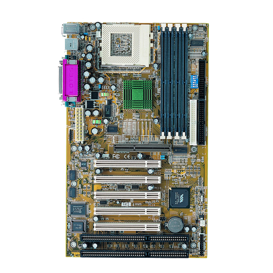
FA13 Mainboard Manual Quick Reference (from Page 2-2 to 2-4) Mainboard Layout NOTE: 1. The PCI5 slot is shared with the (optional) ISA1 Slot. 2. The PCI5 slot only allows a slave card on it. 2 - 2... - Page 17 Installation Procedures CPU/BUS Speed Ratio Select, Clear CMOS, Clear Password, FSB Speed Select, Over Voltage Driving, Keyboard Power On 2 - 3...
- Page 18 FA13 Mainboard Manual Front Panel Block Cable Connection CPU Fan Installation 2 - 4...
- Page 19 Installation Procedures 1). Set System Switches/Jumpers NOTE: When SW1-6 set at Enabled, the keyboard password (K/B Wake-up function, BIOS Setup) will be cleared too. Users can power on the system by pushing power button. 2 - 5...
- Page 20 FA13 Mainboard Manual NOTE: To use this function and WOL connector together, your power supply should have a current of above 1A at 5 V Stand-by. WARNING: Voltage and frequency above CPU’s specifications are not guaranteed to be stable. 2 - 6...
- Page 21 Installation Procedures 2). Install RAM Modules RAM Module Configuration Install and Remove DIMMs 2 - 7...
-
Page 22: Install The Cpu
FA13 Mainboard Manual 3). Install the CPU CAUTION: 1. Always turn the system power off before installing or removing any device. 2. Always observe static electricity precautions. See “Handling Pre- cautions” at the start of this manual. 3. Inserting the chip incorrectly may damage the chip. - Page 23 Installation Procedures CPU/FSB Speed Ratio Select 2 - 9...
-
Page 24: Fsb Speed Select
FA13 Mainboard Manual FSB Speed Select 2 - 10... -
Page 25: Install Expansion Cards
Installation Procedures 4). Install Expansion Cards NOTE: 1. The PCI5 slot is shared with the (optional) ISA1 Slot. 2. The PCI5 slot only allows a slave card on it. CAUTION: Make sure to unplug the power supply when adding or removing expansion cards or other system components. - Page 26 FA13 Mainboard Manual 2 - 12...
-
Page 27: Connect Devices
Installation Procedures 5). Connect Devices 2 - 13... - Page 28 FA13 Mainboard Manual NOTE: The power supply must provide +3.3V voltage. Ò 2 - 14...
- Page 29 Installation Procedures 2 - 15...
- Page 30 FA13 Mainboard Manual 2 - 16...
- Page 31 Installation Procedures 2 - 17...
- Page 32 FA13 Mainboard Manual 2 - 18...
- Page 33 Installation Procedures NOTE: USB3 connector is manufacturing optional. 2 - 19...
- Page 34 FA13 Mainboard Manual This Page Left Blank for Note 2 - 20...
-
Page 35: Cmos Setup Utility
BIOS Setup Chapter 3 BIOS Setup CMOS Setup Utility 3 - 1... -
Page 36: Standard Cmos Setup
FA13 Mainboard Manual Standard CMOS Setup Hard Disk Configurations Software Turbo Speed 3 - 2... -
Page 37: Bios Features Setup
BIOS Setup BIOS Features Setup Anti-Virus Protection CPU Internal Cache External Cache Processor Number Feature Boot From LAN First 3 - 3... - Page 38 FA13 Mainboard Manual Boot Sequence Swap Floppy Drive Boot Up Floppy Seek Boot Up Numlock Status Gate A20 Option Memory Parity Check Typematic Rate Setting 3 - 4...
- Page 39 BIOS Setup Security Option PCI/VGA Palette Snoop OS Select For DRAM > 64MB HDD S.M.A.R.T. Capability Report No FDD For WIN 95 Video BIOS Shadow 3 - 5...
-
Page 40: Chipset Features Setup
FA13 Mainboard Manual BIOS Guardian NOTE: Please disable this BIOS feature about BIOS Guardian before you start to reflash BIOS. Chipset Features Setup Bank 0/1 DRAM Timing; Bank 2/3 DRAM Timing; Bank 4/5 DRAM Timing; Bank 6/7 DRAM Timing SDRAM Cycle Length... - Page 41 BIOS Setup DRAM Clock Memory Hole Read Around write Concurrent PCI/Host Video RAM Cacheable System BIOS Cacheable Video RAM Cacheable 3 - 7...
- Page 42 FA13 Mainboard Manual AGP Aperture Size AGP-2X Mode OnChip USB USB Keyboard Support Auto Detect DIMM/PCI Clk CPU Clock/Spread Spectrum 3 - 8...
-
Page 43: Power Management Setup
BIOS Setup Power Management Setup ACPI function 3 - 9... - Page 44 FA13 Mainboard Manual Power Management PM Control by APM Video Off After Video Off Method MODEM Use IRQ Soft-Off by PWR-BTTN 3 - 10...
- Page 45 BIOS Setup HDD Power Down Doze Mode Suspend Mode LPT & COM 3 - 11...
- Page 46 FA13 Mainboard Manual HDD & FDD DMA/master Modem Ring Resume RTC Alarm Resume Date (of Month) Timer (hh:mm:ss) Wake Up On LAN 3 - 12...
- Page 47 BIOS Setup Power On on by PCI card Primary INTR IRQs Activity Monitoring 3 - 13...
-
Page 48: Pnp/Pci Configuration
FA13 Mainboard Manual PNP/PCI Configuration PNP OS Installed Resources Controlled By Reset Configuration Data CPU to PCI Write Buffer 3 - 14... - Page 49 BIOS Setup PCI Dynamic Bursting PCI Master 0 WS Write PCI Delay Transaction PCI#2 Access #1 Retry AGP Master 1 WS Write AGP Master 1 WS Read PCI IRQ Actived By 3 - 15...
-
Page 50: Load Bios Defaults
FA13 Mainboard Manual Assign IRQ For VGA Slot 1&5/2/3/4 Use IRQ No. Load BIOS Defaults 3 - 16... - Page 51 BIOS Setup Load Setup Defaults Integrated Peripherals 3 - 17...
- Page 52 FA13 Mainboard Manual OnChip IDE Channel0 OnChip IDE Channel1 IDE Prefetch Mode IDE HDD Block Mode Primary Master PIO Primary Slave PIO 3 - 18...
- Page 53 BIOS Setup Secondary Master PIO Secondary Slave PIO Primary Master/Slave UDMA Secondary Master/Slave UDMA NOTE: two features Primary UDMA Cable and Secondary UDMA Cable were added. Please stay with the default value 40 Pin when you use a 40- pin cable for your 33MHz hard drive/CD-ROM. Please select the option 80 Pin when you use a 80-pin cable for your 33MHz (or 66MHz) hard drive/CD-ROM.
- Page 54 FA13 Mainboard Manual KB Power On Password Hot Key Power ON KBC input clock Onboard FDC Controller Onboard Serial Port 1 3 - 20...
- Page 55 BIOS Setup Onboard Serial Port 2 UART Mode Select UART2 Duplex Mode RxD , TxD Active IR Transmission Delay Onboard Parallel Port Parallel Port Mode 3 - 21...
-
Page 56: Supervisor/User Password
FA13 Mainboard Manual ECP Mode Use DMA EPP Mode Select PWRON After PWR-Fail Supervisor/User Password 3 - 22... - Page 57 BIOS Setup IDE HDD Auto Detection Save and Exit Setup Exit without Saving 3 - 23...
- Page 58 FA13 Mainboard Manual This Page Left Blank for Note 3 - 24...
Need help?
Do you have a question about the FA13 and is the answer not in the manual?
Questions and answers