Grundfos SMART Digital XL DDA 60-10 Installation And Operating Instructions Manual
Hide thumbs
Also See for SMART Digital XL DDA 60-10:

Related Manuals for Grundfos SMART Digital XL DDA 60-10


Summary of Contents for Grundfos SMART Digital XL DDA 60-10
- Page 1 GRUNDFOS INSTRUCTIONS SMART Digital XL - DDA From 60 to 200 l/h Installation and operating instructions Further languages http://net.grundfos.com/qr/i/98767821...
-
Page 2: Table Of Contents
English (GB) Installation and operating instructions Alarm Original installation and operating instructions 7.3.3 Setup 7.3.4 CONTENTS Operation modes Manual 7.4.1 Page Pulse 7.4.2 General information 7.4.3 Analog 0/4-20 mA Symbols used in this document Batch (pulse-based) 7.4.4 Qualification and training Dosing timer cycle 7.4.5 Safety instructions for the operator/user... -
Page 3: General Information
Resetting the service system 1.2 Qualification and training Diaphragm leakage The persons responsible for the installation, 8.6.1 Dismantling the dosing head, diaphragm operation and service must be appropriately and valves in case of diaphragm leakage qualified for these tasks. Areas of responsibility, 8.6.2 Dosing liquid in the pump housing levels of authority and the supervision of the persons... -
Page 4: Safety Of The System In The Event Of A
1.4 Safety of the system in the event of a 1.6 Diaphragm leakage failure in the dosing pump If the diaphragm leaks or is broken, dosing liquid escapes from the drain opening on the dosing head. The dosing pump was designed according to the See fig. -
Page 5: Diaphragm Leakage Detection (Optional)
2. Storage and handling 1.6.1 Diaphragm leakage detection (optional) Applies to DDA-AR control variant. 2.1 Storage Pumps with diaphragm leakage detection (DLD) have a special dosing head with a special diaphragm • Observe the permissible ambient conditions. See and a pressure switch. The pressure switch is fitted section 4. -
Page 6: Product Introduction
Excellent dosing features of the pump: permitted. Grundfos cannot be held liable for any • Optimal intake even with degassing media, as damage resulting from incorrect use. -
Page 7: Symbols On The Pump
3.3 Symbols on the pump Symbol Description Indication of universally dangerous spot. In case of emergency and prior to all maintenance work and repairs, take the mains plug out of the power supply! The device complies with electrical safety class I. 3.4 Nameplate Type IP 65... -
Page 8: Type Key
Japan SS + integrated diaphragm leakage Argentina SS-L detection Design Gasket material DDA 60-10 FCM-PVC/V/C-F-31U3U3FG DDA 60-10 FCM-PVC/V/C-F-31U3U3FG Grundfos red EPDM Grundfos green Grundfos black PTFE Neutral / black Valve ball material Special variant DDA 60-10 FCM-PVC/V/C-F-31U3U3FG DDA 60-10 FCM-PVC/V/C-F-31U3U3FGC3... -
Page 9: Product Overview
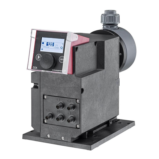
3.6 Product overview Pos. Description section Control cube Graphic LC display 7.2.2 Click wheel [100%] key Signal inputs/outputs Mounting plate Mains connection [Start/stop] key Dosing head Valve, outlet side Deaeration valve Connection, deaeration hose Pressure switch of diaphragm leakage detection (optional for DDA-AR) FlowControl sensor plug (only DDA-FCM) -
Page 10: Technical Data / Dimensions
4. Technical data / Dimensions 4.1 Technical data Data 60-10 120-7 200-4 Turn-down ratio (setting range) [1:X] [l/h] Max. dosing capacity [gph] 15.8 52.8 [l/h] Max. dosing capacity with SlowMode 50 % [gph] 26.4 [l/h] Max. dosing capacity with SlowMode 25 % [gph] 3.95 13.2... - Page 11 Data 60-10 120-7 200-4 Voltage 100-240 V ± 10 %, 50/60 Hz Length of mains cable Max. inrush current for 2 ms (100 V) Max. inrush current for 2 ms (240 V) Electrical data Max. power consumption P Enclosure class IP65, Nema 4X Electrical safety class Pollution degree...
-
Page 12: Technical Data For Cip (Clean-In-Place)
4.2 Technical data for CIP (Clean-In-Place) applications Short-term temperature limits for max. 40 minutes at max. 2 bar operating pressure: Max. liquid temperature for dosing head material PVDF [°C] Max. liquid temperature for dosing head material stainless steel [°C] The dosing head material Polyvinyl chloride (PVC) must not be used in CIP applications. 4.2.1 Dimensions 4 x Ø... -
Page 13: Assembly And Installation
5. Assembly and installation 5.1.3 Installing the pump on the mounting plate 1. Remove the locking screws from their transport 5.1 Pump assembly position on the mounting plate. 2. Place the pump on the mounting plate support Install the pump in such a way that the clamps and slide it in as far as possible. -
Page 14: Adjusting The Control Cube Position
4. Carefully lift off the control cube only so far from Faultless function can only be guaranteed in the pump housing that no tensile stress is conjunction with lines supplied by Grundfos. produced on the flat band cable. The lines used must comply with the pressure limits –... - Page 15 Hose connection, type U3U3 Pipe connection, type U3U3 For details on connection types, see section For details on connection types, see section 3.5 Type key. 3.5 Type key. 1. Make sure the system is pressureless. 1. Make sure the system is pressureless. 2.
-
Page 16: Electrical Connection
Pipe connection, types A1A1, A3A3, A7A7 5.3 Electrical connection For details on connection types, see section The mains plug is the separator separating the pump 3.5 Type key. from the mains. 1. Make sure the system is pressureless. All electrical connections must be carried out by a 2. - Page 17 Signal connections WARNING Electric shock Death or serious personal injury - Electric circuits of external devices connected to the pump inputs must be separated from dangerous voltage by means of double or reinforced insulation! Fig. 12 Wiring diagram of the electrical connections Symbol Function Pin assignment 1/brown...
-
Page 18: Startup
FlowControl signal connection (DDA-FCM) 6. Startup 6.1 Preparing the pump for startup CAUTION Chemical hazard Minor or moderate personal injury - Observe the material safety data sheet of the dosing medium. - Wear protective clothing (gloves and goggles) when working on the dosing head, connections or lines. -
Page 19: Setting The Menu Language
6.3 Setting the menu language For description of control elements, see section 7. Operation 1. Turn click wheel to highlight the cog symbol. 60.0 Manual Operation 2. Press the click wheel to open the "Setup" menu. 60.0 Manual Setup 3. Turn the click wheel to highlight the "Language" menu. -
Page 20: Deaerating The Pump
6.4 Deaerating the pump 1. Read section 6.1 Preparing the pump for startup. 2. Open the deaeration valve by approximately half a turn. WARNING Pressurised dosing medium Death or serious personal injury - Do not open the deaeration valve by more than one full turn. - Page 21 6.5.1 Calibration process - example for DDA 60-10 1. Fill a measuring beaker with dosing medium. Recommended filling volumes V – DDA 60-10: 2.5 l – DDA 120-7: 5 l = 2.5 l – DDA 200-4: 8 l 2. Read off and note down the fill volume V (e.g.
-
Page 22: Operation
7. Operation 7.2 Display and symbols 7.2.1 Navigation 7.1 Control elements In the "Info", "Alarm" and "Setup" main menus, the The pump control panel includes a display and the options and submenus are displayed in the rows following control elements. below. -
Page 23: Overview Of Display Symbols
7.2.4 Overview of display symbols The following display symbols may appear in the menus. Top row with main menus (Sect. 7.3) Operation Back Info Alarm Run display Running - rotates when pump is dosing Setup Blocked drive - flashing symbol Operation 59.6 Manual... -
Page 24: Main Menus
Counters 7.3 Main menus The "Info > Counters" menu contains the following The main menus are displayed as symbols at the top counters: of the display. The currently active main menu is displayed as text. Counters Resettable 7.3.1 Operation Volume Status information such as the dosing flow, selected operation mode and operating state Total dosed volume [l] or US gallons... -
Page 25: Setup
7.3.4 Setup 7.4 Operation modes The "Setup" main menu contains menus for Six different operation modes can be set in the pump configuration. These menus are "Setup > Operation mode" menu. described in the following sections. Manual, see section • 7.4.1 Check all pump settings after any change in the Pulse, see section... -
Page 26: Pulse
7.4.2 Pulse 7.4.3 Analog 0/4-20 mA In this operation mode, the pump doses the In this operation mode, the pump doses set dosing volume for each incoming (potential-free) according to the external analog signal. The pulse, e.g. from a water meter. The pump dosing volume is proportional to the signal input automatically calculates the optimum stroke value in mA. -
Page 27: Batch (Pulse-Based)
Set analog scaling Set analog scaling in the "Operation" menu Analog scaling refers to the assignment of the Analog scaling can also be modified after a security current input value to the dosing flow. prompt directly in the "Operation" menu. This is how the dosing flow is directly modified for the current Changes of analog scaling affect also the analog flow input value. -
Page 28: Dosing Timer Cycle
7.4.5 Dosing timer cycle The batch volume (e.g. 75.0 l) is set in the "Setup > Batch volume" menu. The minimum dosing time In this operation mode, the pump doses the required for this (e.g. 1 hour, 16 minutes) is set batch volume in regular cycles. -
Page 29: Dosing Timer Week
The total batch volume (e.g. 6.83 l) and the If several procedures overlap, the process with the remaining batch volume still to be dosed are higher dosing flow has priority. displayed in the "Operation" menu. During breaks in In the event of an interruption (e.g. disconnection of dosing, the time until the next dosing process (e.g. -
Page 30: Analog Output
7.5 Analog output 7.6 SlowMode When the "SlowMode" function is enabled, the Analog out pump slows down the suction stroke. The function is enabled in the "Setup > SlowMode" menu and is Output = Input used to prevent cavitation in the following cases: Actual flow ❑... -
Page 31: Stop After Power Failure
7.7 Stop after power failure This function is only available in pumps with software version V2.00 or higher. The "Stop after power failure" function is used to prevent the pump from performing a reference movement and start dosing when the power supply is switched on or reestablished after a power failure. -
Page 32: Flowcontrol
7.8 FlowControl FlowControl works with a maintenance-free sensor in the dosing head. During the dosing process, the Applies to DDA-FCM control variant. sensor measures the current pressure and This function is used to monitor the dosing process. continuously sends the measured value to the Although the pump is running, various influences microprocessor in the pump. -
Page 33: Pressure Monitoring
Delay 7.9.2 Calibration of pressure sensor The "Delay" parameter is used to define the time The pressure sensor is calibrated in the factory. As a period until an error message is generated: "short", rule, it does not need to be re-calibrated. If specific "medium"... -
Page 34: Flow Measurement
7.10 Flow measurement Example of "AutoFlowAdapt" Pressure fluctuations Applies to DDA-FCM control variant. The dosing volume decreases as backpressure The pump accurately measures the actual flow and increases and conversely the dosing volume displays it. Via the 0/4-20 mA analog output, the increases as the backpressure decreases. -
Page 35: Key Lock
7.14 Key lock 7.15.2 Additional display The additional display provides additional The key lock is set in the "Setup > Key lock" information about the current pump status. The value menu by entering a four-digit code. It protects the is shown in the display with the corresponding pump by preventing changes to settings. -
Page 36: Time+Date
7.16 Time+date 7.17.2 Possible industrial bus types The pump can be connected to a Grundfos CIU unit The time and date can be set in the "Setup > (CIU = Communication Interface Unit) equipped with Time+date" menu. one of the following CIM modules (CIM =... -
Page 37: Setting The Bus Address
7.17.4 Setting the bus address 7.17.6 Deactivate communication 1. Enter "Setup > Bus" menu and set desired bus After deactivating the bus control function, the pump address: can start automatically. CAUTION Bus type Address range Automatic startup ® Profibus 0-126 Minor or moderate personal injury Modbus RTU 1-247... -
Page 38: Inputs/Outputs
7.18 Inputs/Outputs 7.18.1 Relay outputs The pump can switch two external signals using In the "Setup > Inputs/Outputs" menu, you can installed relays. The relay outputs are potential-free. configure the two outputs "Relay 1+Relay 2" and the The connection diagram of the relays is shown in signal inputs "External stop", "Empty signal"... -
Page 39: External Stop
Timer Cycle (Relay 2) 7.18.3 Empty and Low level signals For the "Relay 2 > Timer Cycle" function, set the In order to monitor the filling level in the following parameters: tank, a dual-level sensor can be connected to the pump. -
Page 40: Service
Maintenance work must only be carried out [h]* by qualified persons. Service soon! 7500 The pump housing must only be opened Service now! by persons authorised by Grundfos. 8000 Observe section Repairs. Since the last service system reset 8.1 Regular maintenance Interval... -
Page 41: Perform Service
8.4 Perform service Only spare parts and accessories from Grundfos should be used for maintenance. The usage of non-original spare parts and accessories renders any liability for resulting damages null and void. CAUTION Chemical hazard Minor or moderate personal injury - Observe the material safety data sheet of the dosing medium. -
Page 42: Service Overview
8.4.1 Service overview 5a 5b 1d 1f 1b 1c 9 9a Fig. 44 DDA 60-10 5a 5b 1d 1f 1b 1c 9 9a Fig. 45 DDA 120-7 / DDA 200-4 Pos. Components Pos. Components Cover plate (plastic dosing heads only) Deaeration screw Washers (stainless steel dosing heads 1a, 1e O-ring... -
Page 43: Dismantling The Dosing Head, Diaphragm
16. Check the safety diaphragm (10) for wear and torque wrench before startup and every damage. If the safety diaphragm is damaged, time the dosing head has been opened. send the pump to Grundfos for repair. See After 48 operating hours, retighten the section Repairs. -
Page 44: Replacing The Deaeration Valve
(1c). This procedure requires a special tool kit. See service kit catalogue: 18. Manually screw in deaeration screw (1). • http://net.grundfos.com/qr/i/96488862_23 19. Deaerate the dosing pump. See section 6.4 Deaerating the pump. 20. Observe the notes on commissioning in section Startup. -
Page 45: Diaphragm Leakage
14. Check the safety diaphragm (10) for wear and damage. If the safety diaphragm is damaged, To avoid any danger resulting from diaphragm send the pump to Grundfos for repair. See leakage, observe the following: section Repairs. •... -
Page 46: Repairs
"Alarm" main menu, which can cause supplier. If your local Grundfos supplier asks you to the pump to start. send the pump to Grundfos for repair, fill in the safety CAUTION declaration in English and attach it to the pump for shipping. -
Page 47: List Of Faults
9.1 List of faults 9.1.1 Faults with error message Display in the Possible cause Possible remedy "Alarm" menu Empty • Dosing medium tank empty • Fill tank. (Alarm) • Check plug connection. Low level • Check contact setting (NO/NC). • Dosing medium tank almost empty (Warning) •... - Page 48 Motor blocked • Incorrectly installed diaphragm • Install the diaphragm correctly. (Alarm) • Damage to gears • Contact your Grundfos service partner. • Hall sensor failure • Motor failure • Fieldbus communication error • Check cables for correct specification and Bus error damage;...
- Page 49 Display in the Possible cause Possible remedy "Alarm" menu • Leaky/dirty outlet valve. Dosing • Replace valve if necessary. See section medium flows back from the outlet 8.4 Perform service. line into the dosing head and • Install screen in inlet line. Disch.
-
Page 50: General Faults
10. Disposal This product or parts of it must be disposed of in an environmentally sound way. Use appropriate waste collection services. If this is not possible, contact the nearest Grundfos company or service workshop. See also end-of-life information at www.grundfos.com/product-recycling. - Page 51 Appendix Safety declaration Please copy, fill in and sign this sheet and attach it to the pump returned for service. Fill in this document using English or German language. Product type (nameplate) Model number (nameplate) Dosing medium Fault description Please make a circle around the damaged parts. In the case of an electrical or functional fault, please mark the cabinet.
- Page 52 Argentina China Germany Bombas GRUNDFOS de Argentina S.A. Grundfos Alldos GRUNDFOS Water Treatment GmbH Ruta Panamericana km. 37.500 Centro Dosing & Disinfection Reetzstraße 85 Industrial Garin ALLDOS (Shanghai) Water Technology D-76327 Pfinztal (Söllingen) 1619 - Garin Pcia. de B.A. Co. Ltd.
- Page 53 Phone: +40 21 200 4100 Telefax: +66-2-725 8998 Phone: +82-2-5317 600 Telefax: +40 21 200 4101 Turkey Telefax: +82-2-5633 725 E-mail: romania@grundfos.ro GRUNDFOS POMPA San. ve Tic. Ltd. Latvia Russia Sti. SIA GRUNDFOS Pumps Latvia ООО Грундфос Россия Gebze Organize Sanayi Bölgesi Deglava biznesa centrs ул.
- Page 54 98767821 0219 ECM: 1246835 www.grundfos.com...
Need help?
Do you have a question about the SMART Digital XL DDA 60-10 and is the answer not in the manual?
Questions and answers