Table of Contents
Advertisement
Advertisement
Table of Contents

Related Manuals for Grundfos DDI 209


Summary of Contents for Grundfos DDI 209
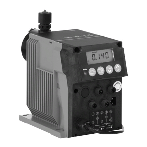
- Page 1 GRUNDFOS INSTRUCTIONS DDI 209 Dosing pump Installation and operating instructions...
-
Page 2: Declaration Of Conformity
BG Декларация за съответствие We, Grundfos, declare under our sole responsibility Ние, фирма Grundfos, заявяваме с пълна that the products DDI 209, to which this declaration отговорност, че продуктите DDI 209, за които се relates, are in conformity with these Council отнася... - Page 3 ES Declaración de Conformidad Εμείς, η Grundfos, δηλώνουμε με αποκλειστικά δική Meie, Grundfos, deklareerime enda ainuvastutusel, μας ευθύνη ότι τα προϊόντα DDI 209 στα οποία et tooted αναφέρεται η παρούσα δήλωση, συμμορφώνονται DDI 209, mille kohta käesolev juhend käib, on με...
- Page 4 RU Декларация о соответствии A Grundfos declara sob sua única responsabilidade Мы, компания Grundfos, со всей que os produtos DDI 209, aos quais diz respeito ответственностью заявляем, что изделия DDI esta declaração, estão em conformidade com as 209, к которым относится настоящая...
- Page 5 FI Vaatimustenmukaisuusvakuutus V Grundfosu s polno odgovornostjo izjavljamo, da Me, Grundfos, vakuutamme omalla vastuullamme, so naši izdelki DDI 209, na katere se ta izjava että tuotteet DDI 209, joita tämä vakuutus koskee, nanaša, v skladu z naslednjimi direktivami Sveta o ovat EY:n jäsenvaltioiden lainsäädännön...
-
Page 6: Table Of Contents
Mounting These installation and operating instructions contain Installation examples all the information required for starting up and handling the DDI 209 diaphragm dosing pump. Installation tips Tube / pipe lines If you require further information or if any problems arise, which are not described in detail in this... -
Page 7: Information About The Product
1.3 Information about the product 1.3.1 Pump types The DDI 209 dosing pump is available for a variety of performance ranges in various sizes: Pump types DDI 0.4-10 DDI 2.2-16 DDI 2.5-10 DDI 5.5-10 DDI 13.8-4 DDI 20-3 The following is indicated on the pump nameplate (see section 4.1 Identification):... - Page 8 1.3.3 Pump performance Performance data at maximum pump counter-pressure Normal operation Slow-mode operation Max. Max. Pump type With p max.* stroke With p max.* stroke Standard Plus rate Standard Plus rate system system [l/h] [l/h] [bar] [n/min] [l/h] [l/h] [bar] [n/min] DDI 0.4-10 0.4***...
- Page 9 1.3.4 Accuracy Minimum counter-pressure at the pump discharge valve • Applies to: – water as dosing medium Operating conditions / version* – fully deaerated dosing head – standard pump version. Pump type All* • Dosing flow fluctuation and linearity deviation: ±...
- Page 10 92 % (non-condensing). Power supply for AC voltage Warning • Rated voltage range: 110-240 V. The DDI 209 is NOT approved for Deviation from the rated value: ± 10 %. operation in potentially explosive • Mains frequency: 50/60 Hz. areas! •...
- Page 11 1.3.10 Dosing medium For degassing dosing media, note the following: • The DDI 209 without Plus system can be used in In the event of questions regarding the flooded suction for moderately degassing media material resistance and suitability of such as chlorine bleaching agents.
-
Page 12: Applications
Note easier and ensure safe operation. 1.4.1 Appropriate, acceptable and correct usage The DDI 209 pump is suitable for liquid, Information provided directly on the pump, e.g. non-abrasive and non-inflammable media strictly in labelling of fluid connections, must be observed and accordance with the instructions in this manual. -
Page 13: Qualification And Training Of Personnel
Leakages of dangerous substances (e.g. hot, toxic) DDI 209 dosing pumps are designed according to must be disposed of in a way that is not harmful to the latest technologies and are carefully the personnel or the environment. -
Page 14: Transport And Intermediate Storage
Do not throw or drop the pump. 4. Technical data 3.2 Delivery 4.1 Identification The DDI 209 dosing pump is delivered in a cardboard box. Place the pump in the packaging during transport and intermediate storage. 3.3 Unpacking Retain the packaging for future storage or return, or dispose of the packaging in accordance with local regulations. -
Page 15: Type Key
4.2 Type key Example: DDI 2- 16 AR PVC /V /G -F -3 1 3 B1 B Type range Mains plug No plug Maximum flow [l/h] EU (Schuko) Maximum counter-pressure [bar] USA, Canada Control variant Australia, New Zealand, Taiwan Standard Switzerland AR with Flow Monitor Connection, suction/discharge... -
Page 16: General Description
4.3 General description Option: The pump can also be equipped with the following: The DDI 209 is a dosing pump with a stepper motor and electronic power control. The pump is operated • Flow Monitor via the diagonal or horizontal display in a •... - Page 17 4.3.2 DDI 209 Plus system with priming and calibration system for moderately degassing liquids (chlorine bleaching agents) (only for DDI 209 0.4-10 to DDI 209 5.5-10) Fig. 3 DDI 209 Plus system 4.3.3 Functional principle of the Plus system Pos.
- Page 18 Fig. 4 Functional principle of the Plus system 4.3.4 DDI 209 with diaphragm leakage detection Fig. 5 DDI 209 with diaphragm leakage detection Pos. Components Suction valve Discharge valve Dosing head with flange for diaphragm leakage detection Connection for deaeration line...
- Page 19 4.3.5 Functional principle of diaphragm leakage detection Pumps with diaphragm leakage detection (MLS) have a special dosing head flange for an optoelectronic sensor. The pump is supplied with the diaphragm leakage sensor (MLS) already installed. The optoelectronic sensor contains: • infrared transmitter •...
-
Page 20: Dimensional Sketches
4.4 Dimensional sketches Fig. 7 DDI 209 Dimensions for DDI 209 c HV d HV e HV [mm] [mm] [mm] [mm] [mm] [mm] DDI 0.4-10 175.5 G 3/8 175.5 G 3/8 DDI 2.2-16 175.5 G 3/8 207.5 G 5/8 DDI 2.5-10 175.5... - Page 21 G 3/8 DDI 2.2-16 G 3/8 DDI 2.5-10 G 3/8 DDI 5.5-10 G 3/8 Fig. 9 DDI 209 with diaphragm leakage detection Dimensions for DDI 209 with diaphragm leakage detection c1 HV d1 HV e1 HV [mm] [mm] [mm] [mm] [mm] [mm] DDI 0.4-10...
-
Page 22: Weight
(stores a maximum of Remote on/off Maximum load: 12 V, 5 mA 65,000 pulses) • two-stage tank-empty signal (e.g. via Grundfos Tank-empty signal Maximum load: 12 V, 5 mA tank-empty sensor) Dosing controller and diaphragm leakage sensor •... -
Page 23: Installation
5. Installation 5.3 Mounting Carefully tighten the screws, otherwise 5.1 General information on installation Caution the plastic housing may be damaged. Warning 5.3.1 Horizontal mounting Observe the specifications for the installation location and range of applications described in sections 1. General information and 5.2 Installation location. -
Page 24: Installation Examples
5.4 Installation examples Fig. 12 Installation example of pump with manual deaeration -[p] Pos. Components Dosing tank Electric agitator Extraction device Dosing pump Relief valve Pressure-loading valve Calibration tube 1.5 m Injection unit > 10 mm < 1.5 m >... -
Page 25: Installation Tips
5.5 Installation tips • To avoid the siphon effect, install a pressure-loading valve (7i) in the discharge line • For non-degassing media with a viscosity similar and, if necessary, a solenoid valve (14i) in the to water, the pump can be mounted on the tank suction line. -
Page 26: Tube / Pipe Lines
• In the case of long discharge lines, install a Warning non-return valve (12i) in the discharge line. Observe the pressure stage of the used lines. The maximum permissible inlet pressure and the pressure stage of the discharge lines must not be exceeded! Minimum internal diameter Pump version Pump type... -
Page 27: Electrical Connections
Observe the local safety regulations! Warning The pump housing must only be opened by personnel authorised by Grundfos! Fig. 22 Plus system Warning Protect the cable connections and plugs against corrosion and humidity. -
Page 28: Connecting The Signal Lines For Ddi
6.1 Connecting the signal lines for DDI 209 Fig. 24 DDI 209 connection diagram 6.1.1 Diaphragm leakage signal Socket 1 For diaphragm leakage signal (MLS). The diaphragm leakage signal is pre-assembled with an M12 plug for socket 1. • Connect the cables according to the table below. - Page 29 (product number Note 96645265) has to be applied as described in section 6.1.6 Accessories: cable and plug for DDI 209. 6.1.3 Stroke/pulse signal / pre-empty signal / error signal Socket 3 Electrically isolated output for stroke/pulse signal or pre-empty signal and error signal.
- Page 30 6.1.4 Remote on/off / contact input / current input Socket 4 For the remote on/off input and contact input or current input. If the remote on/off and contact inputs are to be used at the same time, wire 1 is assigned twice. For the connection of one cable, use a plug adapter with simple cable entry, Caution...
-
Page 31: Connecting The Power Supply Cable
6.1.6 Accessories: cable and plug for DDI 209 Description Product numbers 4-pole M12 plug, suitable for socket 3, with 2 m signal cable 96609017 / 321-206 4-pole M12 plug, suitable for socket 3, with 5 m signal cable 96609019 / 321-208... - Page 32 7.1.2 Assisting suction for Plus system Pumps with Plus system have an assisting suction. • Fit the syringe and the piece of hose. Fig. 25 Assisting suction for Plus system Warning Ensure that the pump is stopped! Sucking in dosing medium using the assisting suction for Plus system Fig.
- Page 33 Sucking in dosing medium using the assisting suction Fig. 28 Sucking in the dosing medium 1. Attach the hose to the connection for the deaeration line. 2. Open the deaeration screw, 1 or 2 turns. 3. Draw up the syringe in order to create a perceptible low pressure, and hold the syringe in this position.
-
Page 34: Operating The Pump
7.1.4 Assisting suction for systems without Plus 7.2 Operating the pump system To operate the pump, see sections At the dry suction/discharge valves: 8. Operation and 10. Maintenance and, 1. Remove the suction line. Note if necessary, section 11. Fault finding 2. -
Page 35: Operation
1. Close the isolating valve (D) at the calibration tube (E). Fig. 30 Display of DDI 209 2. The supply from the priming chamber (F) is shut off and the calibration tube (E) is slowly emptied. 3. Using a stop watch, measure the time (t in... -
Page 36: Deaeration
9. How to use the control unit 8.4 Deaeration First see sections 5. Installation, 7. Start-up / shutdown and Note 7.2 Operating the pump. Only the additional functions are described in this section. 9.1 Menu levels Menu levels used in the control unit •... - Page 37 3. For a pre-empty signal, relay 1 must be set to "Pre-empty signal". See sections 6.1 Connecting the signal lines for DDI 209 and 9.7.1 Modifying the switch assignment. When the contact of the corresponding float switch closes, Fig.
-
Page 38: Signal Outputs
9.2.6 Remote on/off The following errors are recognised: The pump can be switched off remotely (e.g. from a • Pressure exceeded (the pump is stopped and control room). restarts automatically when the pressure decreases). • If switched off remotely, the pump does not respond to any input signals or to operator input. -
Page 39: First Function Level
9.4 First function level Pump not running (LED lights up red) Menu Pump running (LED lights up green) Info Manual Manual control 1.20 Set the dosing rate to approx. Stop Down 1 % to 100 % of max. dosing Start rate [l/h] Menu Info... - Page 40 The maximum displayed/adjustable flow rate is Even if the pump receives more contact signals than automatically set according to the selected pump it can process at the maximum flow rate, it only runs type and the calibrated stroke volume. in continuous operation with a maximum stroke frequency of 180/min.
-
Page 41: Second Function Level
9.5 Second function level 9.5.1 Opening / exiting the second function level Open the second function level • to set the access code, • to enable or disable functions such as Flow Monitor or memory, • to enter settings for operating modes such as batch mode, •... - Page 42 Pump running (LED lights up green) Stop Stop Start Start Pump not running (LED lights up red) Menu Stop Info Start Keep pressed for 3 seconds Second function level Down Setting code 111 Menu Info • Calibration • Timer mode •...
- Page 43 Stop Start Menu Stop Info Start Keep pressed for 3 seconds Down Setting code 111 Code Stop C:111 Start Menu Info Calibration Press "Up" to start calibration, Down Stop see section 9.6 Calibration Start Menu Info Flow Monitor Dosing controller Stop Down Active: only with Flow Monitor...
-
Page 44: Calibration
Setting code 111 Calibration Dosing controller See previous page Pressure control Memory function Weighting of current input/output Stop Menu Start Info Batch on/off ON / OFF Batch Stop Down Adjustment of batch quantity and Start dosing rate for batch operation, see section 9.6.5 Batch menu / batch mode Menu... - Page 45 "OFF CAL" appears in the display. 4. Use the "Up" and "Down" buttons to enter the calibration value (gauged volume in ml). 1. Press the "Up" button. • Press the "Menu/Info" button (confirm the setting – "ON CAL" appears in the display. and move on to the next menu item), or 2.
- Page 46 9.6.1 Calibrating pumps with Plus system 4. Press the "Start/Stop" button. (internal calibration) – The current calibration value is displayed 1. Before opening the second menu level, close the (not with replacement circuit boards!). isolating valve (D) on the calibration tube (E) and 5.
-
Page 47: Service Level
9.6.2 Flow Monitor 9.6.9 Display/resetting of total dosing capacity In order for the pressure sensor (if installed) to The total capacity dosed since the value was last function as a dosing controller, the dosing controller reset is displayed. must be switched on, see section 9.10 Flow Monitor. The maximum value that can be 9.6.3 Memory function displayed is 9999 l. - Page 48 Pump not connected to power supply Menu Down Info Keep pressed when switching on LED alternately flashes red and green Stop Stop Start LED lights up yellow Stop Start Menu Info Service level 1. Relay function (stroke / pre-empty / pulse selection) 2.
- Page 49 1. Relay function (stroke / pre-empty / pulse 5. Error signal, NO/NC output selection) "5:NO" or "5:NC" appears in the display ("ERROR" "1:OFF", "1:ON" or "1:1:1" appears in the display. flashes in the display). • Use the "Up" and "Down" buttons to switch •...
-
Page 50: Resetting To Default Settings
FE: e.g. "7" (only for Flow Monitor) 9.9 Current signal control 0-20 mA / 4-20 mA • Use the "Up" and "Down" buttons to set the "number of error strokes permitted during For controlling the dosing pump via an external operation". - Page 51 The assignment between the current signal and flow rate is linear. • With 0-20 mA current signal control, the curve for current input and current output passes through Q = 0 at 0 mA and the value pair Q ) at max.
- Page 52 9.9.1 Direct weighting of the current signal input The curve for current input/current output now and output passes as follows: Weighting while the pump is running can be carried • With 0-20 mA (4-20 mA) current signal control, out in the first function level. The currently set value the curve for current input and current output increases or decreases for the maximum flow rate passes linearly through Q = 0 at 0 mA (4 mA) and...
- Page 53 / mA Q [l/h] select mA max. a select mA max. a max. max. 10 l/h 8 l/h 6 l/h select mA max. b 4 l/h select mA min. a select mA min. max. min. / mA min. select mA max. b max.
- Page 54 Menu Stop Info Start 0-20 mA Analog 0-20 mA Analog 0-20 mA Analog 0-20 mA Analog Stop l / h l / h L:0.0 0.000 2.00 Start Down Down Flashing Set the flow rate Q Select value for current mA min. input mA 0-0.999 l/h min.
- Page 55 Result of weighting In the example, the following values were entered as reference points L and H In the example, the following values were entered as reference points L and H : mA = 2 mA, Q = 12 l/h min.
- Page 56 Note down the set current weighting in the following diagram for current input/current output: 1. Label the Q [l/h] axis for your working area. 2. Mark your reference points with the value pairs: L: mA min. select mA min. H: mA in the diagram.
-
Page 57: Flow Monitor
9.10 Flow Monitor 9.10.2 Setting the Flow Monitor In order for the pressure sensor (if installed) to 9.10.1 Application notes function as a dosing controller, the dosing controller must be switched on. Dosing of degassing media (H , chlorine bleaching agents) To allow the pump to switch off in the event of overpressure and to set the cut-off pressure of the •... - Page 58 "P:ON" in the display: The start-up operation is completed 1. Press the "Start/Stop" button. • after 60 strokes. – The currently defined cut-off pressure is shown • after the first valid stroke signalled by the dosing in the display. The default value is the controller.
- Page 59 Pressure exceeded Pump restart attempts: If, after three successive strokes, the cut-off • First the pump makes four attempts to restart, pressure is exceeded, this is recognised as an error: each separated by a 2-second pause, if the chamber pressure has fallen below the cut-off •...
- Page 60 Once the error has been corrected, If the sensor fault cannot be corrected • press the "Start/Stop" button to restart the pump. immediately and if the pump is to – The pump returns to the state it was in before continue to run without a sensor, Note the error occurred.
- Page 61 Calibration of sensor Service level Menu Stop Info Start Calibration of pressure sensor P:OFF P:ON Prepare the pump first! P:- - - Stop P:CAL Start Wait approximately 2 seconds Fig. 64 Calibration of pressure sensor 1. Open the service level. 2.
-
Page 62: Batch Menu / Batch Mode
9.11 Batch menu / batch mode Batch mode is controlled at the first and second function levels. In batch mode, a defined batch quantity is dosed • The batch quantity is set in the second function with a defined dosing flow. The batch can be dosed level. -
Page 63: Timer Menu / Timer Mode
Stop/start of pump during batch dosing 9.12 Timer menu / timer mode To stop the pump, In timer mode, a defined batch quantity is dosed with • press the "Start/Stop" button, or a defined dosing flow. The first dosing starts after the start time t has elapsed. - Page 64 Menu Info Menu Info Stop 6.00 890.0 Stop 6.00 890.0 Stop Stop Start Start Start Start Down Down Down Down Down Down Menu Menu Stop 1:00 Info 1:00 Stop Info Start Start Down Down 2:00 Stop Stop 2:00 Stop Stop Start Start Start...
-
Page 65: Creating A Master/Slave Application
During timer dosing Alternatively select the current output (output socket 2) for current control of the slave pump. The batch quantity still to be dosed appears in the display. Please note that the current output can To display the batch quantity already dosed, differ from the current input, e.g. -
Page 66: Hotkeys / Info Keys
9.14 Hotkeys / info keys The following important displays and functions of the DDI 209 can be accessed quickly using button combinations (hotkeys). Service functions Operating state of the Activate function / Deactivate function / Function pump display display Press the "Start/Stop"... -
Page 67: Maintenance
2. Remove the valve tube (R) with the valve (3c). opened by personnel authorised by 3. Unscrew the valve (3c) from the valve tube. Grundfos! Repairs must only be carried out by authorised and qualified personnel! Switch off the pump and disconnect it... -
Page 68: Replacing The Diaphragm
10.4.2 Switching off the pump For contents and product numbers of the 1. Switch off the pump and disconnect it from the spare parts kits, contact Grundfos. power supply. 4. Re-assemble and refit the valve. 2. Depressurise the system. - Page 69 After initial start-up and after each time the diaphragm is changed, tighten the dosing head screws. After approximately 6-10 operating hours or two days, cross-tighten the Caution dosing head screws using a torque wrench. Maximum torque: DDI 0.4 - DDI 5.5: 2.1 Nm. DDI 13.8 - DDI 20: 2.5 Nm.
-
Page 70: Fault Finding Chart
Leaking suction line. Replace or seal the suction line. not suck in. Cross-section of the suction line too Check with Grundfos specification. small or suction line too long. Clogged suction line. Rinse or replace the suction line. Foot valve covered by sediment. -
Page 71: Disposal
12. Disposal This product or parts of it must be disposed of in an environmentally sound way: 1. Use appropriate waste collection services. 2. If this is not possible, contact the nearest Grundfos company or service workshop. Subject to alterations. - Page 72 Appendix Safety declaration Please copy, fill in and sign this sheet and attach it to the pump returned for service. We hereby declare that this product is free from hazardous chemicals, biological and radioactive substances: Product type: ____________________________ Model number: _________________________ No media or water: _________________________ A chemical solution, name: _____________________ (see pump nameplate)
- Page 74 Argentina China Germany Bombas GRUNDFOS de Argentina S.A. Grundfos Alldos GRUNDFOS GMBH Ruta Panamericana km. 37.500 Lote Dosing & Disinfection Schlüterstr. 33 ALLDOS (Shanghai) Water Technology 40699 Erkrath 1619 - Garin Co. Ltd. Tel.: +49-(0) 211 929 69-0 Pcia. de Buenos Aires West Unit, 1 Floor, No.
- Page 75 Fax: + 370 52 395 431 Тел. (+7) 495 737 30 00, 564 88 00 Turkey Факс (+7) 495 737 75 36, 564 88 11 Malaysia GRUNDFOS POMPA San. ve Tic. Ltd. E-mail grundfos.moscow@grundfos.com GRUNDFOS Pumps Sdn. Bhd. Sti. Serbia 7 Jalan Peguam U1/25 Gebze Organize Sanayi Bölgesi...
- Page 76 Thinking ahead makes it possible Innovation is the essence 91834768 0812 ECM: 1062500 The name Grundfos, the Grundfos logo, and the payoff Be–Think–Innovate are registrated trademarks owned by Grundfos Management A/S or Grundfos A/S, Denmark. All rights reserved worldwide. www.grundfos.com...
Need help?
Do you have a question about the DDI 209 and is the answer not in the manual?
Questions and answers