Table of Contents
Advertisement
Quick Links
Advertisement
Table of Contents

Related Manuals for IFM ZZ0600


Summary of Contents for IFM ZZ0600
- Page 1 Instructions for set-up Fluid monitoring system Application solution...
-
Page 2: Table Of Contents
Fluid monitoring system - Application solution Contents 1 Preliminary note � � � � � � � � � � � � � � � � � � � � � � � � � � � � � � � � � � � � � � � � � � � � � � � � � � � � � � � � � � � � � � � � � � � �3 1�1 Symbols used �... -
Page 3: Preliminary Note
Fluid monitoring system - Application solution 1 Preliminary note You will find detailed instructions, technical data, approvals and further information using the QR code on the individual units / packagings or at www�ifm�com� 1.1 Symbols used Instruction ► > Reaction, result Designation of keys, buttons or indications […]... -
Page 4: Safety Instructions
Fluid monitoring system - Application solution 2 Safety instructions ● The devices described are integrated into a system as components� – The system manufacturer is responsible for the safety of the system� – The system creator undertakes to perform a risk assessment and to create documentation in accordance with legal and normative requirements to be provided to the operator and user of the system�... -
Page 5: Function
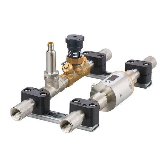
4 Function 4.1 Fluid monitoring system The ZZ0600 fluid monitoring system contains the following components: ● SM6000 flow meter for monitoring and display of the flow temperature and the cooling water volumetric flow quantity� The setting of 2 switch points allows the detection of overflow (leakage / burst pipes / worn caps). - Page 6 Fluid monitoring system - Application solution LR DEVICE LR SMARTOBSERVER ZZ0600 Fig� 1: Application solution overview A: Preconfigured industrial PC B: Application package consisting of: 1: Power supply 2: AL13nn IO-Link master 3: SM6000 flow meter 4: TA2405 temperature sensor...
-
Page 7: Installation
Fluid monitoring system - Application solution 5 Installation ► Disconnect the power of the machine before installation� ► Adhere to the instructions enclosed to the individual devices� 5.1 Fluid monitoring system ► Mount the fluid monitoring system in the cooling water process� ►... -
Page 8: 6�1 Pin Assignment Of The Io-Link Master
Fluid monitoring system - Application solution 6.1 Pin assignment of the IO-Link master AL1300 / AL1320 / AL1330 / AL1340 1: Fieldbus (optional) 2: Fieldbus (optional) 3: Power supply 4: IoT interface to the industrial PC with LR DEVICE 5: SM6000 6: TA2405 7: not connected 8: not connected... -
Page 9: 7�1 Set Up The Industrial
> The Windows desktop interface of the industrial PC appears� 7.2 Create a backup copy of the operating system ifm recommends you to create a backup copy of the Windows operating system before continuing to work with the industrial PC�... -
Page 10: 7�3 Set Up Lr Device
Fluid monitoring system - Application solution ► [Control Panel] > [All Control Panel Items] > [Backup and Restore (Windows 7)] ► Click on [Create a system image]� > A dialogue window appears� ► Select the destination for the backup copy� ►... -
Page 11: 7�4 Adapt The Calculation Of The Heat Quantity
During parameter setting the sensors remain in the operating mode� They continue to monitor with the existing parameter until the parameter setting has been completed� The sensors' IODD at www�ifm�com contains a complete list of adjustable parameters� 8.1 Change limit values and switch points... -
Page 12: Operation
Fluid monitoring system - Application solution ► In the [ONLINE] area: Click on the IO-Link master found� > LR DEVICE shows the sensors connected to the ports� ► Click on Port ([P1: SM6000] or [P2: TA2405]). > Adjustable parameters of the connected sensor are displayed� ►... - Page 13 Fluid monitoring system - Application solution In the [Cockpit] section: ► Under [FMS]: Select the application tag of the requested fluid monitoring system (e�g� fluid monitoring system 1-1). ► In the status line: Select the [AUTO] tab� > The window shows the current process values of the selected fluid monitoring system� Explanation: Display Description...
Need help?
Do you have a question about the ZZ0600 and is the answer not in the manual?
Questions and answers