Table of Contents
Advertisement
Quick Links
Advertisement
Table of Contents

Related Manuals for IFM ZZ0600


Summary of Contents for IFM ZZ0600
- Page 1 Instructions for set-up Fluid monitoring system Application package...
-
Page 2: Table Of Contents
Fluid monitoring system - Application package Contents 1 Preliminary note � � � � � � � � � � � � � � � � � � � � � � � � � � � � � � � � � � � � � � � � � � � � � � � � � � � � � � � � � � � � � � � � � � � �3 1�1 Symbols used �... -
Page 3: Preliminary Note
Fluid monitoring system - Application package 1 Preliminary note You will find detailed instructions, technical data, approvals and further information using the QR code on the individual units / packagings or at www�ifm�com� 1.1 Symbols used Instruction ► > Reaction, result Designation of keys, buttons or indications […]... -
Page 4: Safety Instructions
Use of media from group 1 fluids on request� 4 System requirements A PC is required for the installation of the LR DEVICE parameter setting software� For the system requirements please see the LR DEVICE software manual at www�ifm�com�... -
Page 5: Function
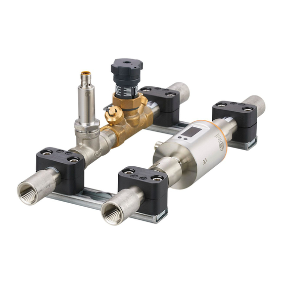
5 Function 5.1 Fluid monitoring system The ZZ0600 fluid monitoring system contains the following components: ● SM6000 flow meter for monitoring and display of the flow temperature and the cooling water volumetric flow quantity� The setting of 2 switch points allows the detection of overflow (leakage / burst pipes / worn caps). -
Page 6: Installation
2: AL13nn IO-Link master 3: SM6000 flow meter 4: TA2405 temperature sensor 5: ifm memory stick with LR DEVICE parameter setting software 6 Installation ► Disconnect the power of the machine before installation� ► Adhere to the instructions enclosed to the individual devices�... -
Page 7: 6�3 Power Supply
Fluid monitoring system - Application package ► Use 2 mounting screws and washers of size M5 for fixing�Tightening torque: 1�8 Nm� 6.3 Power supply ► Integrate the power supply into the control cabinet� The following has to be observed: – Suited for DIN rails according to EN 60715 with a height of 7�5 or 15 mm� –... -
Page 8: Set
LR DEVICE allows the parameter setting of the IO-Link master and the connected sensors� ► Start the PC� ► Log in with administrator rights� ► Install the LR DEVICE parameter setting software from the ifm memory stick to PC (→ Software manual LR DEVICE). ► Start LR DEVICE�... -
Page 9: Parameter Setting
During parameter setting the sensors remain in the operating mode� They continue to monitor with the existing parameter until the parameter setting has been completed� The sensors' IODD at www�ifm�com contains a complete list of adjustable parameters� 6.1 Change limit values and switch points... -
Page 10: Operation
Fluid monitoring system - Application package 7 Operation 7.1 Monitor the process data In normal operation, LR DEVICE can display the process data of the application package graphically� In LR DEVICE: ► Click on the symbol [ ] to scan the network for available devices� IO-LINK >...
Need help?
Do you have a question about the ZZ0600 and is the answer not in the manual?
Questions and answers