Table of Contents
Advertisement
Quick Links
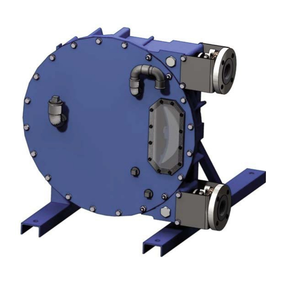
PUMPS A65 - AS65
Z.I. La Plaine des Isles - F 89000 AUXERRE - FRANCE
Tel. : +33 (0)3.86.49.86.30 - Fax : +33 (0)3.86.49.87.17
contact@mouvex.com - www.mouvex.com
INSTRUCTIONS 1101-J00 e
Section
1101
Effective
August 2010
Replaces
July 2010
Original instructions
INSTALLATION
OPERATION
MAINTENANCE
Your distributor :
Advertisement
Table of Contents

Subscribe to Our Youtube Channel
Related Manuals for Dover PSG MOUVEX A65


Summary of Contents for Dover PSG MOUVEX A65
- Page 1 INSTRUCTIONS 1101-J00 e Section 1101 Effective August 2010 Replaces July 2010 Original instructions PUMPS A65 - AS65 INSTALLATION OPERATION MAINTENANCE Your distributor : Z.I. La Plaine des Isles - F 89000 AUXERRE - FRANCE Tel. : +33 (0)3.86.49.86.30 - Fax : +33 (0)3.86.49.87.17 contact@mouvex.com - www.mouvex.com...
-
Page 2: Table Of Contents
MOUVEX PERISTALTIC HOSE PUMP SAFETY INSTRUCTIONS, STORAGE, INSTALLATION AND MAINTENANCE MODELS : A65 - AS65 TABLE OF CONTENTS Page TECHNICAL CHARACTERISTICS 1. OVERALL DIMENSIONS ......3 •... -
Page 3: A65 Model
with PN16 flanges with PN20 flanges with PN16 flanges A (1:4) with PN20 flanges A (1:4) 4 holes Ø 19 [0.748] 4 holes Ø 18 [0.709] 8 holes Ø 18 [0.709] Thermal sensor emplacement, to choose according rotation direction (see ATEX Instructions). -
Page 4: Overall Dimensions
1. OVERALL DIMENSIONS (continued) 1.2 AS65 model NT 1101-J00 08.10 A65 - AS65 e... -
Page 5: Installation
2. INSTALLATION 2.1 Operator principle 2.4 Pipe diameters The pump operates by alternating contraction and The location of the pump in the transfer or recycling circuit relaxation of a specially designed elastomeric hose. should always be determined so as to reduce the suction height and length of the piping as much as possible. -
Page 6: Direction Of Rotation
2. INSTALLATION (continued) 2.8 Working with vaccum on the suction side If the liquid may freeze or solidify, prepare for draining the piping by installing drain taps at the low points and Because of the operating principle of the pump, using it air vents at the high points. -
Page 7: Anchoring The Pump Units
2. INSTALLATION (continued) 2.11 Anchoring the pump units It is important to control the alignment at every step of installation in order to ensure that none of these steps The correct seating of the pump is vital for its efficient generates stress on the pump unit or the pump itself : operation and its longevity. -
Page 8: Use
3. USE 3.1 Pump storage 3.5 Starting-up the pump If the pump is inactive for more than 3 months, remove WARNING the hose or the shoes. If you do not wish to remove the hose or the shoes, operate the pump for 5 minutes once FAILURE TO RELIEVE THE SYSTEM a week. -
Page 9: Maintenance Operations
4. MAINTENANCE OPERATIONS WARNING WARNING IF PUMPING HAZARDOUS OR TOXIC DISCONNECT THE ELECTRICITY SUP- FLUIDS, THE SYSTEM MUST BE FLUSHED PLY BEFORE ANY MAINTENANCE OPE- PRIOR TO PERFORMING ANY SERVICE RATION. OPERATION. Hazardous or toxic Dangerous voltage. fluids can cause Can cause injury and death serious injury. - Page 10 4. MAINTENANCE OPERATIONS (continued) TOP PORT NOTES If the pump is not re-assembled immediately, dry Repeat the steps described above from 2 to 10. unpainted surfaces and coat them with the pump lubricant in order to protect them against corrosion. WARNING Dispose of the drained products in accordance with the rules and regulations in force.
- Page 11 4. MAINTENANCE OPERATIONS (continued) BOTTOM PORT 4.1.5 FILLING WITH LUBRICANT 1. Check the state of the nipple 6 and change it if necessary. CAUTION 2. Coat the nipple 6 with pump lubricant. 3. Slide the nipple 6 on the body port 1. 4.
-
Page 12: Re-Assembling And Disassembling The Wheel
4. MAINTENANCE OPERATIONS (continued) 4.2 Re-assembling and disassembling the 7. Slide wheel 3 on the reduction gear or the bearing box wheel shaft. 8. Align wheel 3 with pump body 1 while keeping setting Disassembly and reassembly of the wheel 3 are required distance as indicated on the following diagram : when : Keying distance (L) :... -
Page 13: Setting Of Pump At Service Pressure Needed
4. MAINTENANCE OPERATIONS (continued) CAUTION 4.3.2 ASSEMBLING THE SHOES 1. Check that the shoes have no dents or deep scratches that may quickly deteriorate the hose. THE PUMP LUBRICANT IS VERY SLIPPERY 2. Position the screw 28 with its washer 29 around the AND MAY CAUSE SERIOUS INJURY. - Page 14 4. MAINTENANCE OPERATIONS (continued) CAUTION 4.4.2 FILLING WITH LUBRICANT 1. Unscrew the plug 124. 2. Fill the pump body with lubricant, as indicated in THE PUMP LUBRICANT IS VERY SLIPPERY § LUBRICATION. AND MAY CAUSE SERIOUS INJURY. ANY SPILLS MUST BE CLEANED UP. 3.
-
Page 15: Technical Specifications
5. TECHNICAL SPECIFICATIONS Flowrate (m3/h) 10,1 12,2 14,2 16,2 18,2 45000 10 bar 7,5 bar 5 bar 15 bar 40000 35000 30000 25000 Max service @50°C 20000 Max service @60°C Max service @7 0°C 15000 Max service @80°C 10000 With vacuum assist 5000 Without vacuum assist Continuous service... -
Page 16: Characteristics
5. TECHNICAL SPECIFICATIONS (continued) 5.1 Characteristics 5.2 Shimming the shoes Light grey area : Continuous service (24h/24). Suitable shimming of the shoes lengthens the service life of the hose. Dark grey area : Intermittent service (continually for 2 hours then stopped for 1 hour). 5.2.1 SERVICE PRESSURE SPECIFIED AT ORDER The flow rates shown have been obtained by pumping If the service pressure has been specified at order, the... -
Page 17: Maintenance
6. MAINTENANCE 6.1 Lubrication 6.3 Seals The hose is lubricated with a special mixture. MOUVEX 6.3.1 SHAFT SEAL 26 lubricant is recommended to lengthen the service life of The shaft seal 26 must be replaced if lubricant leakage the hose. is observed near the drip strip, located on the rear side It is recommended to change the lubricant when : of the pump body 1. -
Page 18: Troubleshooting
7. TROUBLESHOOTING PROBLEM POSSIBLE CAUSE SOLUTION THE PUMP Check the connections : WILL NOT There must be 3 phases START Electric power supply failure. The connections are suitable for the voltage (delta-star) If possible, check the parameters for the different motor frequencies (starting torque, power input…) When the pump has not been used for a long Operate the pump intermittently to try to free the wheel... -
Page 19: Certificate Of Conformity
8. CERTIFICATE OF CONFORMITY NT 1101-J00 08.10 A65 - AS65 e...
Need help?
Do you have a question about the PSG MOUVEX A65 and is the answer not in the manual?
Questions and answers