
Related Manuals for DITEC TS35


Summary of Contents for DITEC TS35
- Page 1 IP2373EN • 2020-07-28 Ditec TS35 Technical Manual Automation for swing gates (Translation of the original instructions) www.ditecentrematic.com...
-
Page 2: Table Of Contents
Contents Subject Page General safety precautions Declaration of incorporation of partly completed machinery Machinery Directive Technical specifications Gearmotor dimensions Standard installation Installation Preliminary checks Fastening the brackets Electrical connections Release instructions Routine maintenance plan Troubleshooting Disposal This symbol indicates instructions or notes regarding safety, to which special atten- tion must be paid. -
Page 3: General Safety Precautions
1. General safety precautions Failure to respect the information given in this manual may cause personal injury or damage to the device. Keep these instructions for future reference This installation manual is intended for qualified personnel only. Installation, electrical connections and adjustments must be performed in accordance with Good Working Methods and in compliance with the present standards. -
Page 4: Declaration Of Incorporation Of Partly Completed Machinery
The manufacturer Entrematic Group AB, with headquarters in Lodjursgatan 10, SE-261 44 Landskrona, Sweden, declares that the Ditec TS35AC automation for swing gates: - is designed to be installed on a manual gate to form a machine pursuant to Directive 2006/42/ EC. -
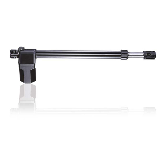
Page 5: Technical Specifications
3. Technical specifications Power supply 230V~ / 50Hz Max absorption 1,5A Power absorbed 330W Capacitor 8µF Max thrust 3500N Maximum stroke 400mm Opening time 18-22s / 90° Intermittence S2= 10min / S3= 30% Lifespan 100000 cycles Operating temperature -20°C / +55°C Degree of protection IP33 Dimensions (mm) -
Page 6: Standard Installation
4. Standard installation Ref. Description Cable Transmitter Flashing light 2 x 1mm² Antenna (integrated in the flashing light) RG58 50Ω Key selector switch 4 x 0,5mm² Digital combination wireless keypad Actuator 4 x 1,5mm² Photocells 4 x 0,5mm² Control panel 3G x 1,5 mm²... -
Page 7: Installation
5. Installation The declared operating and performance features can only be guaranteed with the use of Ditec accessories and safety devices. 5.1 Preliminary checks Make sure the gate structure is sturdy and the hinges are lubricated and smooth. Install a stop in the open and closed positions (the mechanical structural elements must be com- pliant with the requirements of the standard EN12604). -
Page 8: Fastening The Brackets
5.2 Fastening the brackets - Fasten the tail bracket , en- suring that the measurements [A] and [B] are correct for the desired opening angle [D] (see tab. 5.1). screws M10 - not supplied - Fasten the piston to the tail bracket with the pin cluded. - Page 9 - Install the gear motor so that it is inclined by an angle of approximately 1°. 1° - Fit the head bracket and fasten the piston to the head bracket with the pin included. - Unlock the gear motor and check, by moving the gate manually, that the gate moves freely To work correctly, the gear motors must be assembled with the motor casing at the bottom.
-
Page 10: Electrical Connections
The gear motors TS35AC may be connected to the LCA70 and LCA80 electronic control panels. The electrical connections and the procedure for setting up Ditec TS35 gear motors are illustrated in the figure and in the installation manuals of the LCA70 (-> link) and LCA80 (-> link) electronic control panels. -
Page 11: Release Instructions
6. Release instructions In the event of a fault or a power failure, open the window, insert the key in the relative lock and turn it counterclockwise (as indicated by the arrow). Release the electric lock (if present). Manually open the gate. To lock the gate again, close the hatch, turn the key anticlockwise and remove the key. -
Page 12: Troubleshooting
8. Troubleshooting Problem Possible cause Operation No power supply. Make sure the mains supply is active. Gearmotor released. See the release instructions. Check the photocells are clean and op- Photocells occupied. erating correctly. The gate doesn’t Check the STOP command or the con- Permanent STOP command.
Need help?
Do you have a question about the TS35 and is the answer not in the manual?
Questions and answers