Advertisement
Quick Links
MOUNTING
FUNCTIONING
1. Disconnect power supply by the pha-
After power supply switching on it is necessary to set maximum and minimum voltage, hy-
se fuse, the circuit-breaker or the
steresis, phase unbalance and the relay ON-time and OFF-time. If not, the following default
switch- disconnector combined to the
values will be set
proper circuit.
phase voltages are greater or equal to 170 V, automatic phase sequence checking will start.
In case of incorrect phase sequence the output relay will be switched OFF (
2. Check if there is no voltage on con-
will be displayed:
nection cables by means of a spe-
der to set a correct phase sequence will be displayed too. If the phase sequence is correct,
cial measure equipment.
the device will start displaying measured voltages in three-second cycles (see the figure)
3. Install the PNM-32 on the TH-35 DIN
rail in the switchboard.
4. Connect the cables with the terminals
in accordance with the installing dia-
gram.
5. Switch on the power supply from the
mains.
INNER DIAGRAM
cluded within the set range (
threshold exceeding for the given phase will be signalled by displaying the following sym-
bol:
for the minimum threshold
counting the time
KLAW.
LCD
e.g. the L3 phase voltage, the L1 or L2 phase voltage falls below the voltage threshold
or exceeds the min
L1
A/C
to the phase with the incorrect voltage value and will remain in this state until the wrong va-
μC
L2
A/C
lue disappears or the relay is OFF. Układ wykrywa również asymetrię napięcia. The device
A/C
is capable of detecting voltage unbalance. If the potential difference between the phases is
L3
greater than
N
ZAS.
MAIN RESET
DIMENSIONS
CONNECTION
PRODUCT FAMILY
The PNM-32 is a member of the PNM
product family.
Device version:
10 – single phase
31 – three-phase
32 – three-phase, LCD
Device type
WARRANTY CARD
There is 24 months guarantee on the product
1. ZMIE ZAMEL SP. J. assures 24 months guarantee for the product.
2. The manufacturer's guarantee does not cover any of the following actions:
a) mechanical damage during transport, loading / unloading or under other circumstances,
b) damage caused by incorrect product mounting or misuse,
c) damage caused by unauthorised modifications made by the PURCHASER or any third parties to the product or any other devices
needed for the product functioning,
d) damage caused by Act of God or any other incidents independent of the manufacturer.
3. The PURCHASER shall lay any claims in writing to the dealer or ZMIE ZAMEL SP. J.
4. ZMIE ZAMEL SP. J. is liable for processing any claim according to current Polish legislation.
5. ZMIE ZAMEL SP. J. shall process the claim at its own discretion: product repair, replacement or money return.
6. The manufacturer's guarantee is valid in the Republic of Poland.
7. The PURCHASER's statutory rights in any applicable legislation whether against the retailer arising from the purchase contract or
otherwise are not affected by this warranty.
Salesman stamp and signature, date of sale
= 235 V,
= 225 V,
= 1 V,
= 2 s,
= 2 s,
), the symbol
, and a message with info which phases are to be changed over in or-
and voltages controlling.
It is possible to toggle
between the phases by
pressing the cursors
which causes breaking
cyclic phase voltages
display (every 3 s) and
holding the set phase
display for 20 seconds.
If the voltages are in-
,
), after
time the relay will be ON ( ). Any voltage
and the
symbol for the max voltage
, and then will switch OFF the output relay (
). If, during displaying
, threshold, the device will toggle the phase value displayed actually
, the display will show
, and after
time the relay will be OFF (
In order to cancel the circuit data and set de-
fault values it is necessary, in the main win-
dow, to press and hold simultaneously ( and
) keys for 3 seconds;
All display fields will be lighted;
The main window will be entered after a
while.
VOLTAGE RELAY PNM-32
= 10 V. If all
DESCRIPTION
The PNM-32 voltage relay is designed
for the three-phase system voltage con-
trol and load protection. It is possible
to set minimum and maximum voltage,
hysteresis, voltage unbalance and ON
, and start
/ OFF delay. The device is capable of
,
detecting voltage unbalance and phase
sequence. The LCD display and keybo-
ard enable easy parameters visualization
and programming.
).
FEATURES
● Three-phase load protection against
voltage swing and unbalance, and
incorrect phase sequence,
● Measured voltage state indicator,
● Relay state indicator,
● The device supplying with any phase,
● Minimum (170 ÷ 225 V) and maximum
(235 ÷ 290 V) voltage setting,
● OFF-time delay adjustment,
● Voltage control for each phase,
● Correct phase sequence control,
● Voltage unbalance control,
● Relay output - single changeover
contact, maximum load 16 A,
● Mounted on TH 35 rail.
The device is designed for
three-phase installation and
must be installed in accor-
dance with standards valid
in a particular country. The
CAUTION
device should be connec-
ted according to the details
included in this operating manual. Installa-
tion, connection and control should be car-
ried out by a qualified electrician staff, who
act in accordance with the service manual
and the device functions. Disassembling of
the device is equal with a loss of guarantee
and can cause electric shock. Before in-
stallation make sure the connection cables
are not under voltage. The cruciform head
screwdriver 3,5 mm should be used to in-
stal the device. Improper transport, storage,
and use of the device influence its wrong
functioning. It is not advisable to instal the
device in the following cases: if any device
part is missing or the device is damaged or
deformed. In case of improper functioning
of the device contact the producer.
The symbol means selective
collecting of electrical and electronical
equipment. It is forbidden to put
the used equipment together
with other waste
INSTRUCTION MANUAL
Zakład Mechaniki i Elektroniki
ZAMEL sp.j.
J.W. Dzida, K. Łodzińska
ul. Zielona 27, 43-200 Pszczyna, Poland
Tel. +48 (32) 210 46 65, Fax +48 (32) 210 80 04
www.zamelcet.com, e-mail: marketing@zamel.pl
TECHNICAL DATA
PNM-32
Power terminals: L1, L2, L3, N
Rated voltage: 230/400 V AC
Rated voltage tolerance: -15 ÷ +10 %
Rated frequency: 50 / 60 Hz
Rated current: 2 W / 14 VA
Measured voltage indicator: wyświetlacz LCD
Relay state and soft network indicator: wyświetlacz LCD
Voltage unbalance / phase sequence indicator: wyświetlacz LCD
Voltage threshold settings: klawiatura
U min adjustment range: 170 ÷ 225 V
U max adjustment range: 235 ÷ 290 V
Voltage hysteresis adjustment range: 1 ÷ 4 V
Unbalance level adjustment range: 10 ÷ 60 V
OFF-time t off : 2 ÷ 15 s keyboard
ON-time t on : 2 ÷ 15 s keyboard
Time setting accuracy: max ±1 s / 24 h at temp. 25 °C
Voltage measurement accuracy (50 Hz sinus): ±1,5 %*
Output relay parameters: 1NO/NC - 16 A / 250 V AC1 4000 VA
Number of terminal clamps: 12
Section of connecting cables: 0,2 ÷ 2,50 mm
2
Ambient temperature range: -20 ÷ +60
o
C
Operating position: freely
Mounting: rail TH 35 (PN-EN 60715)
Protection degree: IP20 (PN-EN 60529)
Protection level: II
Overvoltage category: II
Pollution degree: 2
Dimensions: double-modular (35 mm) 90x35x66 mm
Weight:
0,12 kg
Reference standards: PN-EN 60730-1; PN-EN 60730-2-1;
PN-EN 61000-4-2,3,4,5,6,11
* The PNM-32 device is not fitted with the True RMS converter and therefore only 50 Hz sinusoidal voltages can be measured correctly;
if there are significant harmonic distortions, the measurement result error may be serious.
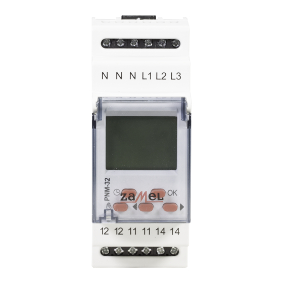
APPERANCE
Power terminal (N)
Power / measure terminals
(L1, L2, L3)
Display
Relay mode
Information field
Values (voltage, time)
Control buttons
Relay output terminals
(12, 11, 14)
VER. 001_14.09.2009
Advertisement

Related Manuals for Zamel PNM-32


Summary of Contents for Zamel PNM-32
- Page 1 * The PNM-32 device is not fitted with the True RMS converter and therefore only 50 Hz sinusoidal voltages can be measured correctly; dance with standards valid if there are significant harmonic distortions, the measurement result error may be serious.
- Page 2 DESCRIPTION ON-TIME AND OFF-TIME SETTING Description of displayed fields and messages - relay ON-time setting, enter by pressing OK; With cursors select time in seconds, setting range: 2÷15 s; - relay state After pressing OK button, changes are saved and the main menu is entered, - unbalance where, with the cursors it is possible to enter another menu item or exit...
Need help?
Do you have a question about the PNM-32 and is the answer not in the manual?
Questions and answers