Table of Contents
Advertisement
Quick Links
Installation and Operation Manual
Manual P/N 5900030 — Manual Revision D — April 2021
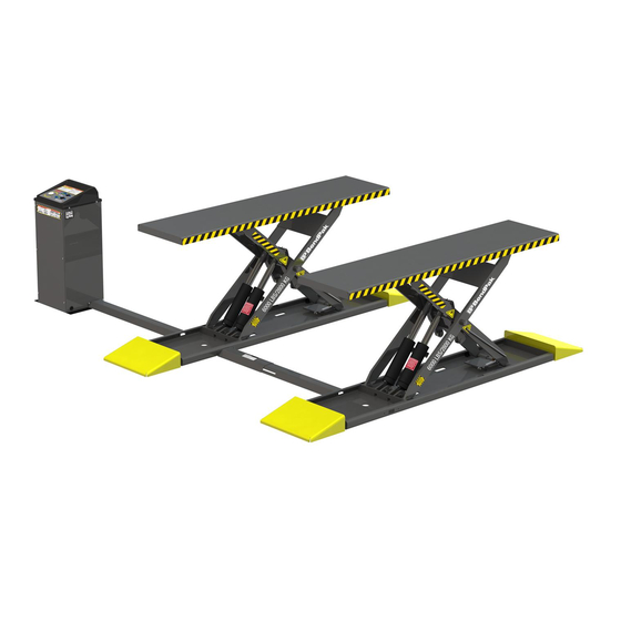
• MDS-6EXT
Models:
Designed and engineered by BendPak Inc. in Southern California, USA. Made in China.
⚠
DANGER
Mid-Rise Scissor Lift
• MDS-6EXTF
entire
Read the
product. Failure to follow the instructions and safety precautions in
this manual can result in serious injury or death. Make sure all other
operators also read this manual. Keep the manual near the product
for future reference. By proceeding with setup and operation,
you agree that you fully understand the contents of this
manual and assume full responsibility of product use .
• MDS-6LP
contents of this manual
1645 Lemonwood Dr.
Santa Paula, CA, 93060 USA
Toll Free: (800) 253-2363
Tel: (805) 933-9970
bendpak.com
• MDS-6LPF
Model MDS-6EXT shown.
before
using this
Advertisement
Table of Contents

Subscribe to Our Youtube Channel
Related Manuals for BendPak MDS-6 Series


Summary of Contents for BendPak MDS-6 Series
- Page 1 Manual P/N 5900030 — Manual Revision D — April 2021 • MDS-6EXT • MDS-6EXTF • MDS-6LP • MDS-6LPF Models: Model MDS-6EXT shown. Designed and engineered by BendPak Inc. in Southern California, USA. Made in China. ⚠ entire before Read the contents of this manual using this product.
- Page 2 Copyright. Copyright © 2021 by BendPak Inc. All rights reserved. You may make copies of this document if you agree that: you will give full attribution to BendPak Inc., you will not make changes to the content, you do not gain any rights to this content, and you will not use the copies for commercial purposes.
-
Page 3: Table Of Contents
Technical support and service is available from your dealer, on the Web at bendpak.com/support, by email at support@bendpak.com, or by phone at (800) 253-2363. You may also contact BendPak for parts replacement information (please have the model and serial number of your unit available) at (800) 253-2363, extension 191. -
Page 4: Shipping Information
Make a visual inspection of the product before using it. Check for damage or missing parts. Do not use the product if you find any issues. Instead, take it out of service, then contact your dealer, email support@bendpak.com, visit bendpak.com/support, or call (800) 253-2363. thorough •... - Page 5 • Use of the product for purposes other than those described in this manual. • Modifications to the equipment without prior, written permission from BendPak Inc. • Injury or death caused by modifying, disabling, overriding, or removing safety features. •...
-
Page 6: Faq
Frequently Asked Questions Question: How much weight can MDS-6 Series Lifts raise? Answer: They can raise Vehicles up to 6,000 pounds (2,722 kg). Q: What is the difference between the MDS-6EXT and MDS-6LP Lifts? extended-length Platforms A: The MDS-6EXT/F has... -
Page 7: Components
Components MDS-6EXT shown without Ramps. Power Unit and Flow Divider are inside the Console. Air and Hydraulic Hoses are routed under the two Covers. Lift components include: • Console. Hosts the Lift Controls (on top) and the Power Unit and Flow Divider (inside). The Air and Hydraulic Hoses connect to the Power Unit inside the Console. -
Page 8: Specifications
Specifications MDS-6EXT and MDS-6EXTF The MDS-6EXT does not include Ramps or Covers. MDS-6 Mid-Rise Scissor Lifts P/N 5900030 — Rev. D — April 2021... - Page 9 Model MDS-6EXT MDS-6EXTF Type Surface Flush-Mount Lifting capacity 6,000 lbs. / 2,722 kg 6,000 lbs. / 2,722 kg A Lifting height (full rise - no 36.75" / 933 mm 36.75" / 933 mm blocks) Lifting height (full rise) 38.25" / 972 mm 38.25"...
- Page 10 MDS-6LP and MDS-6LPF The MDS-6LP does not include Ramps or Covers. MDS-6 Mid-Rise Scissor Lifts P/N 5900030 — Rev. D — April 2021...
- Page 11 Model MDS-6LP MDS-6LPF Type Surface Flush-Mount Lifting capacity 6,000 lbs. / 2,722 kg 6,000 lbs. / 2,722 kg A Lifting height (full rise - no 44.1" / 1,119 mm 44.1" / 1,119 mm blocks) Lifting height 45.6" / 1,158 mm 45.6"...
- Page 12 MDS-6 Series Console Left Front Right Bottom Back MDS-6 Mid-Rise Scissor Lifts P/N 5900030 — Rev. D — April 2021...
-
Page 13: Installation Checklist
Installation Checklist Following are the steps needed to install the Lift. Perform them in the order shown. ☐ 1. Review the installation Safety Rules. ☐ 2. Plan for Electrical Work. ☐ 3. Make sure you have the necessary Tools. ☐ 4. -
Page 14: Installation
Do not install this equipment without reading and understanding this manual and the safety labels on the unit. BendPak recommends referring to the current version of the ANSI/ALI ALIS Standard Safety Requirements for Installation and Service for more information about safely installing, using, and servicing your Lift. - Page 15 Lift itself as well as Concrete specifications and cutouts depending on the model of MDS-6 Lift. Consult with a licensed Electrician, and a Concrete Specialist early in the process to avoid costly mistakes when installing the MDS-6 Series Scissor Lift. •...
- Page 16 Plan Ahead. There are Electrical, Concrete and Air Lines to be routed to the Lift Console and to the Lift itself. Consult with a licensed Electrician, and a Concrete Specialist early in the process to avoid costly mistakes when installing a MDS-6 Series Scissor Lift. ⚠...
- Page 17 Concrete Structures for the MDS-6 Series Lifts: • All the MDS-6 Series Lifts have slightly different dimensions. Pay close attention to the Concrete Cutout/New Pour Dimensions for your specific Lift model. • Concrete Cutouts. The Lifting Frames of a Flush-Mount Lift are installed in a recessed section of the floor, called a Concrete Cutout.
- Page 18 • Floor Material. Concrete Cutouts and New Pour must be surrounded by and created in a Concrete floor; no other surface (asphalt, dirt, anything else) is acceptable. • Planning. There are critical decisions to make before creating your Concrete Cutouts or New Pour: Lift location, Console location, and how far apart the two Lifting Frames will be.
- Page 19 • Do not install the Lift on a secondary floor level or on any ground floor with a basement beneath without written authorization from the building Architect and prior approval of BendPak Inc. • Never drill or cut into a post tensioned slab. Seek qualified personnel to identify cable locations...
- Page 20 Lifiting frames at least 15 to 18 in / 381 to 457 mm away from the exisiting This dimension is labelled Dim. A in the following diagrams. concrete. The following pages detail recommendations for New Pour Concrete on the MDS-6 Series Lifts. MDS-6 Mid-Rise Scissor Lifts P/N 5900030 — Rev. D — April 2021...
- Page 21 MDS-6EXTF – Use the following diagram as recommendations for creating Concrete Cutouts and/or a New Pour for the MDS-6EXTF only. Top View Side View Do not scale drawing. Not all components shown. MDS-6 Mid-Rise Scissor Lifts P/N 5900030 — Rev. D — April 2021...
- Page 22 Distance between the Ramps or find out you made an error on a dimension, it is very difficult to fix. BendPak recommends double checking your plan several times before cutting or pouring Concrete Cutouts. Mark the lift outline in chalk or tape on the floor and attempt a dry-run with the Vehicle to verify that the placement and dimensions are correct, before you cut.
- Page 23 MDS-6LPF Use the following diagram as recommendations for creating Concrete Cutouts and/or a New Pour for the MDS-6LPF only. Top View Side View Do not scale drawing. Not all components shown. MDS-6 Mid-Rise Scissor Lifts P/N 5900030 — Rev. D — April 2021...
- Page 24 Distance between the Ramps or find out you made an error on a dimension, it is very difficult to fix. BendPak recommends double checking your plan several times before cutting or pouring Concrete Cutouts. Mark the Lift outline in chalk or tape on the floor and attempt a dry-run with the Vehicle to verify that the placement and dimensions are correct, before you cut.
- Page 25 MDS-6LP and MDS-6EXT Use the following diagram as recommendations for creating Concrete Cutouts and/or a New Pour for the MDS-6LP and MDS-6EXT. Top View Side View Do not scale drawings. Not all components shown. MDS-6 Mid-Rise Scissor Lifts P/N 5900030 — Rev. D — April 2021...
- Page 26 The figure below details an MDS-6LP mounted on a New Pour. BendPak strongly recommends working with a concrete specialist to plan and create Concrete Cutouts and/or Slabs for the MDS-6 Lift. MDS-6 Mid-Rise Scissor Lifts P/N 5900030 — Rev. D — April 2021...
- Page 27 Create a Floor Plan Make sure to plan out, in advance, where the Lift and Console are going to go: • Clearance. Make sure there is clearance on all sides and above the Lift site. • Console. The Console must be near the Lift; it can be installed on either the left or right side but only on the cylinder end of the Ramps.
- Page 28 Be sure to leave the Lift on a Safety Lock when Hydraulic Hose, Air Line, and Return Line. you raise it. Important: BendPak recommends using the Eye Bolt that comes with the Lift to raise the Platforms off the Bases. ⚠ at least three people...
- Page 29 3. When the Platform gets above the top Safety Lock, lower it back down onto the top Safety Lock. Leave it on the top Safety Lock. 4. Remove the Eye Bolt from the first Platform, install the Eye Bolt on the second Platform. Perform the same procedure on the second Platform.
- Page 30 About Effective Embedment Anchor Bolts (also called Wedge Anchors) get their holding strength from how far down into the Hole the Anchor Bolt’s Expansion Sleeve presses into the Concrete (called Effective Embedment) and how forcefully the Expansion Sleeve presses into the Concrete (based on the width of the hole and how much Torque is applied).
- Page 31 Each Ramp Assembly Base has four holes MDS-6EXT/F or three holes on the MDS-6LP/F for anchoring to the Concrete. Before you anchor your Lift, make sure the two Platforms are correctly aligned. BendPak recommends double checking the work done when creating your Chalk Line Guides.
- Page 32 1. Make sure the Ramp Bases are where you want them. Once you anchor the Bases into place, it is difficult to change the location. Once the Anchor Bolts are torqued into position, they are not easily removed. BendPak strongly recommends making sure the Bases are in the correct location before anchoring the Bases into place.
- Page 33 4. Insert an Anchor Bolt with Washer into each hole, then tap it down into the hole. 5. Make sure the Washer and Nut are in place, then insert the Anchor Bolt into the hole. The Expansion Sleeve of the Anchor Bolt may prevent the Anchor Bolt from passing through the hole in the Base;...
- Page 34 Assemble and Anchor the Console The Hydraulic Hoses, Air Line, and Return Line require the Console to be within 40 inches of the cylinder end of the Lift on either the left or right side. If you want to set up the Console further than 40 inches from your Lift, you will need to have Hydraulic Hoses fabricated that are long enough to reach the Lift from the desired location.
- Page 35 3. Open the Power Unit Console Box and retrieve the Rear, Left Hand and Right Hand sides of the Console as well as four M6 x 12mm Hex Head Bolts. 4. On a flat level surface, place cardboard or rags down to prevent marring the paint and assemble as...
- Page 36 There are four mounting holes in the bottom flange of the Console. You only need to Note: anchor two of the four holes. BendPak recommends installing them diagonally from each other; one in the front right, the other in the left rear, for example.
- Page 37 Even using a hammer or mallet, the Anchor Bolt should only go into the hole part of the way; this is normal. If the Anchor Bolt goes all the way in with little or no resistance, the hole is too large. Once past the hole in the Console Base, the Anchor Bolt eventually stops going down as the Expansion Sleeve contacts the sides of the hole;...
- Page 38 To mount the Power Unit: 1. Find the four supplied M8 x 20 Hex Head Bolts from the Console packaging. The Power Unit is heavy. BendPak recommends having one person hold the Power Unit while a second person bolts it into place.
- Page 39 Hydraulic System Warnings: ⚠ WARNING Failure to observe these warnings can result in serious personal injury including, in rare cases, death. ⚠ The Hydraulic Hoses and connections must be inspected before any attempt to WARNING raise a Vehicle is made. ⚠...
- Page 40 Hydraulic Hoses and Fittings on your Lift, making your new Lift inoperable and unusable. Your Lift is shipped with clean components; however, BendPak strongly recommends that you take secondary precaution and clean all Hydraulic Hoses and Fittings prior to making connections. It is better and less costly to take these extra steps now so that you do not need to take your Lift out of service later to fix issues that could have been prevented at the time of the installation.
- Page 41 Other types of Thread Sealants (like Teflon Tape) can shred during installation or removal and eventually enter the Hydraulic System. Thread Sealant can be used with most Hydraulic Fittings, BendPak recommends using PTFE Thread Sealant with NPT Fittings. To apply Thread Sealant 1.
- Page 42 The following drawing shows the general arrangement of how Hydraulic Hoses are routed to the Hydraulic Cylinders. Your Flow Divider may look differently, but it will also have one input connector and two output connectors, as shown. The Console is on the Left in the drawing. Not to scale. Not all components shown. Some components exaggerated for clarity.
- Page 43 To connect the Hydraulic Hoses: 1. If the Platforms are not already engaged on their top Safety Locks, raise them now, using a Shop Crane or Forklift. Refer to Lift the Platforms off the Bases additional information. 2. If the front and top of the Console are in place, remove them.
- Page 44 7. Locate the Long and the Extra Long Hydraulic Hoses. 8. Connect the Long and Extra Long Hydraulic Hoses to the two connectors on the Flow Divider. It does not matter which line connects to which output connector on the Flow Divider. Finger tighten the connections.
- Page 45 Working with Compression Fittings and Tubing Your Lift comes with ¼ inch, black, polyethylene Tubing (also called Poly-Flo® Tubing) that is used with Compression Fittings to create the Air Lines and Return Line (Cylinder Vent). This section covers Important: Compression Fittings are not the same as Hydraulic Fittings. Compression Fittings only The components involved with Compression Fittings include: •...
- Page 46 Connect the Air Lines The MDS-6 Series Lifts must be raised off the Safety Locks using Hydraulic Power, then air pressure is used to release the Safety Locks so you may lower the Platforms. It is the responsibility of the Lift owner to provide an air pressure supply (minimum 50 psi / 10 CFM, regulated to a maximum of 125 psi).
- Page 47 Tee branches the air off to the first Lift Frame Air Cylinder and also to the second Lift Frame Air Cylinder. before BendPak recommends planning out the path of the Air Line you start cutting the Tubing. 3. Feed the Air Line tubing from the Console to the First Lift Frame.
- Page 48 Connect the Return Lines The Return Line returns Hydraulic Fluid from the Hydraulic Cylinders to the Power Unit’s Hydraulic Fluid Reservoir. Create the Return Line using the ¼ inch black plastic Tubing that came with the Lift; you need to cut it into sections of the appropriate length.
- Page 49 4. Attach an Elbow Compression Fitting with a 3/8 NPTF to one of the Return Line Ports (Cylinder Vent) on the Power Unit. There are two Return Line connectors on the Power Unit; they work the same, so choose the one that is best for you.
- Page 50 Install the Outer Hose Cover (MDS-6EXT and MDS-6LP Only) The Outer Hose Cover measures 40.25 in. / 1,022 mm long and is not adjustable for length. To install the Outer Hose Cover: 1. Retrieve the Outer Hose Cover, four M6 x 25 mm Hex Head Bolts, and four Washers from the Parts Box.
- Page 51 Contact the Electrician The following tasks require a certified Electrician. ⚠ must DANGER All wiring be performed by a licensed, certified Electrician. If someone who is not a certified Electrician attempts these tasks, they could be electrocuted, resulting in serious injury or death. The Electrician needs to: •...
- Page 52 Connect and Prepare the Power Unit The Power Unit comes assembled from the factory. You need to attach it to the back of the Console (described in Assemble and Anchor the Console) and then connect it properly, described in this section.
- Page 53 ⚠ must DANGER All wiring be performed by a licensed, certified Electrician. If someone who is not a certified Electrician attempts these tasks, they could be electrocuted, resulting in serious injury or death. Do not perform maintenance or installation on the Lift without first making sure that main electrical power has been disconnected from cannot the Lift and...
- Page 54 Power Units - Power Ports and Return Ports Location 5585367 5585019 MDS-6 Mid-Rise Scissor Lifts P/N 5900030 — Rev. D — April 2021...
- Page 55 5585002 Fill the Hydraulic Fluid Reservoir The Hydraulic Fluid Reservoir on the Power Unit must be filled with Hydraulic Fluid or automatic When you receive the Lift, the transmission fluid before you begin normal operation of the Lift. Hydraulic Fluid Reservoir is empty The Power Unit will not work correctly until the Reservoir is filled with approved Hydraulic Fluid.
- Page 56 High electrical running current that exceed the motor’s full load amperage (FLA) rating may result in permanent damage to the motor. BendPak strongly recommends you exceed the rated duty cycle of the motor. MDS-6 Mid-Rise Scissor Lifts...
- Page 57 Lubricate the Lift There are 12 Lubrication areas on each Lift Frame: • Two Lubrication points that use Straight Grease Fittings, at both Scissor Joints, both are M6 x 1.0 Straight Grease Fittings. • Six lubrication points with Elbow Grease Fittings. All six are M6 x 1.0 90° Elbow Grease Fittings at the base of the Cylinders.
- Page 58 MDS-6 Mid-Rise Scissor Lifts P/N 5900030 — Rev. D — April 2021...
- Page 59 Add the Drive-Up Ramps (MDS-6LP and MDS-6XLT Only) The MDS-6EXT and MDS-6LP both come with four Drive-up Ramps: two are installed on the front of the Lift and two on the rear. They are identical parts. The flush-mount versions of the MDS-6 do not include Ramps.
- Page 60 Anchor the Console If you have not yet anchored the Console, you must do so now. Refer to Assemble and Anchor the Console for instructions. Install the Console Cover and secure with the eight M6 Hex Head Bolts. Perform an Operational Test ⚠...
- Page 61 10. When the Platforms get to the ground, hold Lower for a couple of more seconds to make sure both Platforms are fully lowered, then release Lower. 11. Wait for one minute. ⚠ WARNING The Power Unit cannot be run continuously. The motor is not rated for continuous duty.
-
Page 62: Operation
Check the Lift. Check the Lift for any missing, heavily worn, or damaged parts. Do not operate the Lift if you find any issues; instead, take it out of service, then contact your dealer, email support@bendpak.com, visit bendpak.com/support, or call (800) 253-2363, extension 196. - Page 63 • Safety Lock Release button. Releases the Safety Locks so the Platforms can be lowered. If you do not press the Safety Lock Release button when pressing the Lower button, the Lift will stop at the closest Safety Lock. Raising a Vehicle This section describes how to position a Vehicle on the Platforms and raise it.
- Page 64 If any part of the Vehicle’s lifting points are not completely over the Platform, carefully drive the Vehicle back off the Lift and then drive it back on to reposition it, making sure to keep the wheels in the middle of the Platforms. ⚠...
- Page 65 6. Walk completely around the Vehicle and make sure there are no obstructions or any other issues that will interfere with the raising of the Lift and the Vehicle. Pay careful attention to overhead clearances. If there are any obstructions, remove them before raising the Vehicle. ⚠...
- Page 66 About Safety Locks Each of the Frame Assemblies on your Lift comes with its own Safety Lock mechanism. Safety Locks hold a raised Vehicle in place once they are engaged. Safety Locks serve two important functions: • Safety. Safety Locks hold the Platforms in place. Once engaged on Safety Locks, the weight of the Vehicle pressing down holds the Platforms in place.
- Page 67 Lowering a Vehicle This section describes how to lower a Vehicle from a raised position. The same instructions and warnings for raising a Vehicle apply to lowering it. • Never exceed the rated capacity of this Lift, 6,000 lbs. / 2,722 kg •...
-
Page 68: Maintenance
• Weekly: Check all labels on the unit. Replace them if they are illegible or missing. • Monthly: Lubricate the grease fittings. BendPak recommends using White Lithium Grease or similar. • Monthly: Check the Hydraulic Fluid levels. Refill if low. -
Page 69: Troubleshooting
Vehicle with No Tires - Fully Lowered When the MDS-6 Series Lift is completely flat and there is too much weight on the Lift Platform, there is no room to develop any upward force. The weight on the Lift must be reduced by at least half or raise the Vehicle off the Lift Platform or Lift Pads in some other manner. -
Page 70: Wiring Diagram
Wiring Diagram Three Power different Power Units are currently approved for use with the MDS-6 Series. Refer to the wiring schematics below to connect power and the Console control pushbuttons. A Power Disconnect Switch and an External Thermal Overload Protection device in accordance with the National Electrical code and CE code Part 1, must be provided by a licensed, certified Electrician. - Page 71 Refer to the wiring schematics below to connect power and the Console control pushbuttons. A Power Disconnect Switch and an External Thermal Overload Protection device in accordance with the must be provided by a licensed, certified National Electrical code and CE code Part 1, Electrician .
- Page 72 Refer to the wiring schematics below to connect power and the Console control pushbuttons. A Power Disconnect Switch and an External Thermal Overload Protection device in accordance with the National Electrical code and CE code Part 1, must be provided by a licensed, certified Electrician .
-
Page 73: Labels
Labels MDS-6 Mid-Rise Scissor Lifts P/N 5900030 — Rev. D — April 2021... - Page 74 MDS-6 Mid-Rise Scissor Lifts P/N 5900030 — Rev. D — April 2021...
- Page 75 MDS-6 Mid-Rise Scissor Lifts P/N 5900030 — Rev. D — April 2021...
-
Page 76: Parts Diagrams
Parts Diagrams MDS-6 Mid-Rise Scissor Lifts P/N 5900030 — Rev. D — April 2021... - Page 77 MDS-6 Mid-Rise Scissor Lifts P/N 5900030 — Rev. D — April 2021...
- Page 78 MDS-6 Mid-Rise Scissor Lifts P/N 5900030 — Rev. D — April 2021...
- Page 79 MDS-6 Mid-Rise Scissor Lifts P/N 5900030 — Rev. D — April 2021...
- Page 80 MDS-6 Mid-Rise Scissor Lifts P/N 5900030 — Rev. D — April 2021...
- Page 81 MDS-6 Mid-Rise Scissor Lifts P/N 5900030 — Rev. D — April 2021...
- Page 82 MDS-6 Mid-Rise Scissor Lifts P/N 5900030 — Rev. D — April 2021...
- Page 83 MDS-6 Mid-Rise Scissor Lifts P/N 5900030 — Rev. D — April 2021...
- Page 84 MDS-6 Mid-Rise Scissor Lifts P/N 5900030 — Rev. D — April 2021...
- Page 85 MDS-6 Mid-Rise Scissor Lifts P/N 5900030 — Rev. D — April 2021...
- Page 86 MDS-6 Mid-Rise Scissor Lifts P/N 5900030 — Rev. D — April 2021...
- Page 87 MDS-6 Mid-Rise Scissor Lifts P/N 5900030 — Rev. D — April 2021...
-
Page 88: Ali Store
Automotive Lift Institute (ALI) Store You probably checked the ALI’s Directory of Certified Lifts (www.autolift.org/ali-directory-of- certified-lifts/) before making your most recent Lift purchase, but did you know the ALI Store (www.autolift.org/ali-store/) offers a wide variety of professional, easy-to-use, and reasonably priced training and safety materials that will make your garage a safer place to work? The ALI Store is your trusted source for workplace safety! Visit today and get the training and materials you need to work safely:... - Page 89 Maintenance Log MDS-6 Mid-Rise Scissor Lifts P/N 5900030 — Rev. D — April 2021...
- Page 90 Maintenance Log MDS-6 Mid-Rise Scissor Lifts P/N 5900030 — Rev. D — April 2021...
- Page 91 Maintenance Log MDS-6 Mid-Rise Scissor Lifts P/N 5900030 — Rev. D — April 2021...
- Page 92 1645 Lemonwood Drive Santa Paula, CA 93060 USA © 2021 BendPak Inc. All rights reserved. bendpak.com...
Need help?
Do you have a question about the MDS-6 Series and is the answer not in the manual?
Questions and answers