Table of Contents
Advertisement
INSTALLATION AND OPERATION MANUAL
12,000 POUND CAPACITY
SURFACE MOUNTED
FULL-RISE SCISSOR LIFTS
MODELS:
XR-12000
VESION B
XR-12000A
VESION B
RECEIVING
The shipment should be thoroughly inspected as soon as it
is received. The signed Bill of Lading is acknowledgement
by the shipping carrier as receipt of this product as listed
in your invoice as being in a good condition of shipment. If
any of these goods listed on this Bill of Lading are missing
or damaged, do not accept goods until the shipping carrier
makes a notation on the freight bill of the missing or dam-
aged goods. Do this for your own protection.
IMPORTANT SAFETY INSTRUCTIONS
SAVE THESE INSTRUCTIONS
PLEASE READ THE ENTIRE CONTENTS OF THIS MANUAL PRIOR TO
INSTALLATION
AND
INSTALLATION AND OPERATION YOU AGREE THAT YOU FULLY
UNDERSTAND AND COMPREHEND THE FULL CONTENTS OF THIS MANUAL.
FORWARD THIS MANUAL TO ALL OPERATORS. FAILURE TO OPER-
ATE THIS EqUIPMENT AS DIRECTED MAY CAUSE INjURY OR DEATH.
BE SAFE
Your new lift was designed and built with safety in mind.
However, your overall safety can be increased with proper
training and thoughtful operation on the part of the operator.
DO NOT operate or repair this equipment without reading
this manual and the important safety instructions shown
inside. Keep this operation manual near the lift at all times.
Make sure that ALL USERS read and understand this
manual.
1
OPERATION.
BY
PROCEEDING
Keep this operation manual near the
machine at all times. Make sure that
all users read this manual.
Santa Paula, CA. 93060, USA
WITH
LIFT
MAN REV F 08-01-13
P/N 5900050
1645 Lemonwood Dr.
Toll Free 1-800-253-2363
Tel: 1-805-933-9970
Fax: 1-805-933-9160
wwwbendpak.com
Advertisement
Table of Contents

Related Manuals for BendPak XR-12000


Summary of Contents for BendPak XR-12000
- Page 1 MAN REV F 08-01-13 P/N 5900050 INSTALLATION AND OPERATION MANUAL 12,000 POUND CAPACITY SURFACE MOUNTED FULL-RISE SCISSOR LIFTS MODELS: XR-12000 VESION B XR-12000A VESION B Keep this operation manual near the machine at all times. Make sure that all users read this manual.
-
Page 2: Warranty / Serial Number Information
Our comprehensive product warranty means more than a commitment to you; it’s also a commitment to the value of your new BendPak lift. For full warranty details and to register your new lift contact your nearest BendPak dealer or visit http:/ / www.bendpak.com/ support/ warranty/... -
Page 3: Definitions Of Hazard Levels
AFTER YOU HAvE GIvEN THE CARRIER A CLEAR RECEIPT. Support claim with copies of the bill of lad- ing, freight bill, invoice, and photographs, if available. BendPak’s willingness to assist in helping you process your claim does not make BendPak responsible for collection of WARNING ! claims or replacement of lost or damaged materials. -
Page 4: Clearances
CLEARANCES XR-12000 LIFT HEIGHT CLEARANCE NOTE: There must be a 1” MIN distance from top of the loaded vehicle to the nearest obstruction when the lift is in a raised position. XR-12000A 264" 6710 CLEARANCE TO FIT RAMPS IN STORAGE CONFIGURATION 12"... -
Page 5: Table Of Contents
TABLE OF CONTENTS Contents Page No. Warranty / Serial Number Information ............. . 2 Definitions of Hazard Levels . -
Page 6: Installer/Operator Agreement/ Protective Equipment
Shop aprons or shop coats may also be worn, however loose-fitting clothing should be avoided. I understand that BendPak lifts are designed to be installed in indoor locations only. Failure to follow instal- Tight-fitting leather gloves are recommended to protect lation instructions may lead to serious personal injury or the technician’s hands when handling parts. -
Page 7: Introduction
INTRODUCTION 1. Carefully remove the crating and packing 2. Check the voltage, phase and proper amperage materials. CAUTION! Be careful when cutting steel requirements for the motor shown on the motor plate. banding material as items may become loose and fall Wiring should be performed by a certified electrician only. -
Page 8: Tools Required
IMPORTANT NOTE BendPak lifts are supplied with installation instructions and concrete fasteners meeting the criteria as prescribed by the American National Standard "Automotive Lifts - Safety Requirements for Construction, Testing, and Validation" ANSI/ALI ALCTV-2006. Lift buyers are responsible for any special regional structural and/or seismic anchoring requirements specified... -
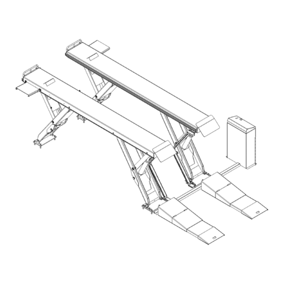
Page 9: Assembly View / Description Of Parts
When removing the lift from shipping angles, pay close attention as the ramps can slide and can cause injury. Prior to removing the bolts make sure the ramps are held securely by a fork lift or some other heavy lifting device. PARTS INvENTORY Be sure to take a complete inventory of parts prior to beginning installation. -
Page 10: Floor Plan / General Specifications
FLOOR PLAN / GENERAL SPECIFICATIONS Measurement XR-12000 XR-12000A A - Overall Extended Length 276.7” / 7029mm 300.3” / 7627mm B - Width w/ Steps 120.4” / 3057mm 120.4” / 3057mm C - Ramp Width 23.8” / 604mm 23.8” / 604mm D - Between Ramps 40.5”... -
Page 11: Step 3 / Site Layout
1. Select an appropriate site for where to install your new function of the lift can occur. state-of-the-art BendPak lift using the chart on page 10. 2. Now determine which direction you would like the lift to face. A vehicle will approach the lift from the Rear Ramp End and drive forward to the Front Ramp End. -
Page 12: Step 4 / Aligning The Ramp Assemblies
STEP 4 (Aligning the Ramp Assemblies) Fig 5.1 1. Lift the Left Ramp Assembly and Right Ramp assem- bly into position and set the ramps down on to the layout created in Step 3 Approach 2. Align the Sliding Pivot Baseplates with the chalklines that were drawn in Step 3. -
Page 13: Step 6 / Hydraulic Hose Connection
3. After drilling, remove dust thoroughly from each hole. 3. Remove port plug from the both ports in the Power Unit and install the 90° Fitting w/ O-ring into the Power 4. Assemble the washers and nuts on the anchors then Port (front port) and the 90°... - Page 14 3. Once the air line hose route has reached the Left 10. Connect the Air Push Button to your compressed air Ramp Assembly’s Rear Safety, cut the air line hose and supply. Be sure that your compressed air supply does not connect a Tee fitting to the air line end.
-
Page 15: Hose Connection/Air Line Routing/Wiring Diagrams
HYDRAULIC HOSE ROUTING DIAGRAM Hose Length 400mm / 15 3/4” 1,956mm / 77” 4,919mm / 193 1/2” 6,043mm / 238” 470mm / 18 1/2” 6,147mm / 242” 11,340mm / 446 1/2” 12,028mm / 473 1/2” Plug... - Page 16 SAFETY AIR LINE ROUTING DIAGRAM LEFT SIDE RIGHT SIDE RAMP RAMP CYLINDER CYLINDER FITTINGS CYLINDER CYLINDER PUSH BUTTON FLOOR APPROACH TROUGHS...
-
Page 17: Step 8 / Power Unit Electrical Connection
220v Wiring Diagram XR-12000 Wiring Diagram (MTE Power Unit) 220V 1 Phase REV B 04-25-13 220V Contactor Motor Down 220V Solenoid 380v Wiring Diagram XR-12000 Wiring Diagram (MTE Power Unit) 380V 3 Phase REV B 04-25-13 Power Unit Console Motor... - Page 18 DANGER! DO NOT PERFORM ANY MAINTENANCE OR INSTALLATION OF ANY COMPONENTS WITH OUT FIRST ENSURING THAT ELECTRICAL POWER HAS BEEN DISCONNECTED AT THE SOURCE OR PANEL AND CANNOT BE RE-ENERGIzED UNTIL ALL MAINTENANCE AND/OR INSTALLATION PROCEDURES ARE COMPLETED. IMPORTANT POWER-UNIT INSTALLATION NOTES n DO NOT run power unit without oil.
-
Page 19: Step 9 / Anchoring The Ramps
ALWAYS WEAR SAFETY GOGGLES. NOTE: 4. Assemble the washers and nuts on the anchors then BENDPAK LIFTS ARE SUPPLIED WITH INSTALLATION INSTRUCTIONS AND CONCRETE FASTENERS MEET- tap into each hole with a hammer until the washer rests ING THE CRITERIA AS PRESCRIBED BY THE AMERI- against the base. -
Page 20: Step 11 / Installing Accessories
2. Using chalk or crayon, mark the floor anchor bolt holes 6. With the shims and Anchor Bolts in place, tighten nut on the concrete. (See Fig. 10.2) three to five turns past finger tight. DO NOT use an impact wrench for this procedure. -
Page 21: Step 12 / Final Assembly
4. Insert the Rollback Spacer Bars between the Turnplate 3. After determining which safeties are not engaging the as needed for alignment procedures. (See Fig 11.3) Safety Ladder, loosen the jam nuts and adjust the position of the ladder until the safety springs into position. Do this for each disengaged Safety Ladder. -
Page 22: Step 14 / Hydraulic Air Bleeding And Leveling
STEP 14 (Hydraulic Air Bleeding and Leveling) READ THE FOLLOWING START-UP INSTRUCTIONS CAREFULLY AND THOROUGHLY. PAY CLOSE ATTENTION TO EACH STEP AS DESCRIBED BELOW IN PRECISE ORDER. IF THESE INSTRUCTIONS ARE NOT FOLLOWED EX- ACTLY, DAMAGE TO THE LIFT CAN OCCUR WHICH IS NOT COVERED UNDER WARRANTY •... - Page 23 • Press the RAISE button until both ramps are approxi- • RAISE or LOWER until the rear of the ramp is level mately 3-4 feet off the ground. with the front. • Stop pressing the RAISE button and close the S3 and •...
- Page 24 Equalization/Leveling Troubleshooting Guide *Note: For reference only. Not assembly instruction Corners S3 and S4 are unequal with S1 and S2 during • Press the LOWER button on the power console until lifting both ramps are at a convenient height for checking level.
- Page 25 Lift will not raise completely • Call customer service immediately. The com- Lower the lift until it reaches floor level. plexity of different situations requires Bendpak experts • CLOSE MAIN valve. to assist you in correctly bringing your lift back to working condition. •...
-
Page 26: Step 15 / Operation
STEP 15 (Operation) To Raise Lift: DANGER! WHEN LOWERING THE LIFT PAY CLOSE Position vehicle tires in the center of each Runway. ATTENTION THAT ALL PERSONNEL AND OBjECTS ARE KEPT CLEAR. ALWAYS KEEP A VISUAL LINE Set parking brake and use Wheel Chocks to hold OF SIGHT ON THE LIFT AT ALL TIMES. -
Page 27: Step 17 / Work Step Installation
STEP 18 Fig 16.1 (Hose Cover Installation) 1. Raise ramps to provide ease of installation for this step. CAUTION! BE AWARE OF RAMP POSITION AND PARTS PROTRUDING FROM RAMPS. INATTENTIVENESS MAY RESULT IN PERSONAL INjURY. 2. Check fitment of the two floor troughs by placing them Leveling Bolts over the hose bundles. -
Page 28: Maintenance / Safe Lift Operation
WEEKLY MAINTENANCE 1. Lubricate all pivot pins with general purpose grease at specified locations found on page 34. NEvER EXCEED THE RATED CAPACITY of lift. 2. Check all component connections, bolts and pins to DO NOT USE LIFT if any component is found to be ensure proper mounting. - Page 29 Safe Lift Operation (Cont’d) t Prior to being raised, make sure there is no one stand- Some vehicle maintenance and repair activities may ing closer than six feet from the lift cause the vehicle to shift. Follow the manufacturer’s guidelines when performing these operations. The use of t After positioning the vehicle on the lift runways, set the jack stands or alternate lift points may be required when emergency brake, make sure the ignition is off, the doors...
-
Page 30: Troubleshooting Guide
7. Oil seal damaged or cocked ......Replace oil seal around pump shaft. 8. See Installation Manual ......Contact BendPak Customer Support. - Page 31 6. Return unit for repair ....... Return unit for repair. 7. See Installation Manual ......Contact BendPak Customer Support.
- Page 32 4. Bleed cylinders ........See Installation Manual. 5. See Installation Manual ......Contact BendPak Customer Support.
- Page 33 See Installation Manual ......Contact BendPak Customer Support. Replace with new part ......Replace with new part.
-
Page 34: Grease Port / Lubrication Locations
Grease Port / Lubrication Locations (Both Ramps) Lubricate Lubricate Once A Week Once A Week Torque Recommendations vAlUES ARE STATED IN FOOT POUNDS (ft-lb) SAE 0-1-2 SAE Grade 5 SAE Grade 8 SOCKET HEAD CAP SCREW CLASS 4.8 CLASS 8.8 CLASS 10.9 CLASS 12.9 Bolt Size... -
Page 35: Maintenance Records
MAINTENANCE RECORDS ____________________________________________________________________ ____________________________________________________________________ ____________________________________________________________________ ____________________________________________________________________ ____________________________________________________________________ ____________________________________________________________________ ____________________________________________________________________ ____________________________________________________________________ ____________________________________________________________________ ____________________________________________________________________ ____________________________________________________________________ ____________________________________________________________________ ____________________________________________________________________ ____________________________________________________________________ ____________________________________________________________________ ____________________________________________________________________ ____________________________________________________________________ ____________________________________________________________________ ____________________________________________________________________ ____________________________________________________________________... -
Page 36: Maintenance Records
MAINTENANCE RECORDS ____________________________________________________________________ ____________________________________________________________________ ____________________________________________________________________ ____________________________________________________________________ ____________________________________________________________________ ____________________________________________________________________ ____________________________________________________________________ ____________________________________________________________________ ____________________________________________________________________ ____________________________________________________________________ ____________________________________________________________________ ____________________________________________________________________ ____________________________________________________________________ ____________________________________________________________________ ____________________________________________________________________ ____________________________________________________________________ ____________________________________________________________________ ____________________________________________________________________ ____________________________________________________________________ ____________________________________________________________________... - Page 44 For Parts Or Service Contact: BendPak Inc. / Ranger Products 1645 Lemonwood Dr. Santa Paula, CA. 93060 Tel: 1-805-933-9970 Toll Free: 1-800-253-2363 Fax: 1-805-933-9160 www.bendpak.com p/n 5900050...
Need help?
Do you have a question about the XR-12000 and is the answer not in the manual?
Questions and answers