Table of Contents
Advertisement
Quick Links
Installation and Operation Manual
Manual P/N 5900085 — Manual Revision A1 — October 2019
:
Models
• XR-12000L
• XR-12000AL
Designed and engineered by BendPak Inc. in Southern California, USA. Made in China.
⚠
DANGER
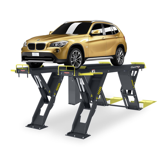
Quatra™ Full-Rise Scissor Lift
Read the
product. Failure to follow the instructions and safety precautions in
this manual can result in serious injury or death. Make sure all other
operators also read this manual. Keep the manual near the product
for future reference. By proceeding with setup and operation, you
agree that you fully understand the contents of this manual.
entire
contents of this manual
1645 Lemonwood Dr.
Santa Paula, CA, 93060 USA
Toll Free: (800) 253-2363
Tel: (805) 933-9970
bendpak.com
XR-12000AL shown.
before
using this
Advertisement
Table of Contents

Related Manuals for BendPak Quatra XR-12000L


Summary of Contents for BendPak Quatra XR-12000L
- Page 1 Installation and Operation Manual Manual P/N 5900085 — Manual Revision A1 — October 2019 Models • XR-12000L • XR-12000AL XR-12000AL shown. Designed and engineered by BendPak Inc. in Southern California, USA. Made in China. ⚠ entire before Read the contents of this manual using this product.
- Page 2 Copyright. Copyright © 2020 by BendPak Inc. All rights reserved. You may make copies of this document if you agree that: you will give full attribution to BendPak Inc., you will not make changes to the content, you do not gain any rights to this content, and you will not use the copies for commercial purposes.
-
Page 3: Table Of Contents
Technical support and service is available from your dealer, on the Web at bendpak.com/support, by email at techsupport@bendpak.com, or by phone at (800) 253-2363, extension 196. You may also contact BendPak for parts replacement information (please have the model and serial number of your unit available) at (800) 253-2363, extension 191. -
Page 4: Shipping Information
Make a visual inspection of the product using it. Check for damage or missing parts. Do not use the product if you find any issues. Instead, take it out of service, then contact your dealer, email techsupport@bendpak.com, visit bendpak.com/support, or call (800) 253-2363. thorough •... - Page 5 BendPak Inc. assumes no liability for damages resulting from: • Use of the product for purposes other than those described in this manual. • Modifications to the equipment without prior, written permission from BendPak Inc. • Damage to the equipment from external influences. •...
-
Page 6: Components
Components Lift components include: • Console. Hosts the Lift Controls and the Power Unit. The Hydraulic Hoses and Air Line connect to the Power Unit inside the Console. • Power Unit. Provides Hydraulic Fluid to the Hydraulic Cylinders, goes inside the Console; connects to an external power source and to the Lift Controls. - Page 7 BendPak website • Rolling Oil Drain Pan. Holds automotive fluid when you are performing oil changes on your Vehicle. See the Rolling Oil Drain Pan page on the BendPak website for more information. Quatra™ Full-Rise Scissor Lift P/N 5900085 — Rev. A1 — October 2019...
-
Page 8: Specifications
Specifications Top View Side View Quatra™ Full-Rise Scissor Lift P/N 5900085 — Rev. A1 — October 2019... - Page 9 Model XR-12000L XR-12000AL Lifting Capacity 12,000 lbs. (5,443 kg) A Lifting height 75" (6.3 feet) / 1,912 mm B Length of Platforms 193" (16.1 feet) / 4,904 mm 218.5" (18.3 feet) / 5,550 mm C Total length with Ramps 276.75" (24 feet) / 7,029 mm 300.25"...
-
Page 10: Faq's
Q: Does it matter if I drive my Vehicles in front first or back them in? A: BendPak strongly recommends driving your Vehicle in front first, because that makes it easier to center the Vehicle’s wheels on the Runways. Also, don’t forget to put the Front Tires up against the Tire Stops and chock the Rear Wheels. -
Page 11: Installation Checklist
Installation Checklist Following are the steps needed to install the Lift. Perform them in the order shown. ☐ 1. Review the installation Safety Rules. ☐ 2. Make sure you have the necessary Tools. ☐ 3. Plan for Electrical Work. ☐ 4. Select the Installation Site. ☐... -
Page 12: Installation
. Use appropriate tools and lifting equipment, when needed. Stay clear of moving parts. BendPak recommends referring to the current version of the ANSI/ALI ALIS Standard Safety Requirements for Installation and Service for more information about safely installing, using, and serving your Lift. - Page 13 Planning for Electrical Work You will need to have a licensed, certified Electrician available at some point during the installation. ⚠ DANGER must All electrical work be performed by a licensed, certified Electrician. Notify your Electrician in advance so that they come prepared with appropriate components for connecting to the power source, a Power Disconnect Switch, and a Thermal Disconnect Switch.
- Page 14 Make sure the floor is defect-free, dry, and level. Only install the Lift on concrete. ⚠ CAUTION BendPak Lifts are supplied with installation instructions and Concrete anchors that meet the criteria set by the current version of the American National Standard “Automotive Lifts — Safety Requirements for Construction, Testing, and Validation”, ANSI/ALI/ALCTV.
- Page 15 Choose the Console Location Before going any further, decide how you want to orient the Console, as it impacts other aspects of the installation. Each Frame has two Hydraulic Hoses (of different lengths) already pre-attached; the Right Frame comes with shorter Hydraulic Hoses, so the Console must go on the right side of the Lift in order for those Hydraulic Hoses to reach the Console where they attach.
- Page 16 Checking Clearances For safety purposes, a certain amount of clear space around the Lift is required . More space is needed at the Rear of the Lift for Vehicles to drive on and off the Platforms. Quatra™ Full-Rise Scissor Lift P/N 5900085 —...
- Page 17 Unloading and Unpacking When the components of your Lift are delivered to the site, have them dropped off as close as possible to the area where you will be installing the Lift. Once the components are unloaded, they are your responsibility to move around. The Frames are very heavy, so the closer you unload them to the installation location, the better off you will be.
- Page 18 Creating Chalk Line Guides Create Chalk Line Guides so that the edges of the Frames fit into the four corners created by the Chalk Line Guides. Length Refer to Specifications to determine the Overall Width and Outside values for your Lift. Overall Note: Do not use the...
- Page 19 Align the Frames into Position Once you have created the Chalk Line Guides, move the Frames into position. To align the Frames into position: 1. Use a Forklift or Shop Crane to lower the Frames into the layout you created. The Frames go on the inside of the Chalk Lines.
- Page 20 Anchor the Console The Console comes assembled from the factory; there are still connections to make to the Power Unit. That will be covered later in the installation. The Rear of the Console must face the Lift to route the Hydraulic Hoses and Air Line through the back opening.
- Page 21 To anchor the Console: 1. Select a site for the Console that permits operators to have a clear, unobstructed view of the Lift. Make sure the Rear of the Console is facing the Lift. 2. Remove the Console from its packaging and move it to the selected location. 3.
- Page 22 Install the Hose Troughs Before you make connections to the Console, attach the Hose Troughs to the Frames; they connect near the Rear of the Frames. The Hose Troughs protect the Hydraulic Hoses and the Air Line as they are routed to the Console. The Hose Troughs are interchangeable;...
- Page 23 To install the Hose Troughs: 1. Raise the Platforms to a height that works for you, then make sure they are engaged on a Safety Lock. You want enough height to attach the Hose Trough near the top of the Platform and by the Base Plate without issue.
- Page 24 Connect the Hydraulic Hoses Hydraulic Hoses provide Hydraulic Fluid to the Hydraulic Cylinders, which are used to raise and lower the Frames. The Hydraulic Hoses on the Lift connect to the Valve Block inside the Console; the Valve Block controls the flow of Hydraulic Fluid to each Hydraulic Cylinder on the Lift. Your Lift comes with the Hydraulic Hoses already pre-attached to the Frames, so you need to connect the Hydraulic Hoses labeled S1 through S4 to the matching Valve on the Valve Block.
- Page 25 The following drawing shows the general arrangement of how the Hydraulic Hoses are routed from the Frames to the Console. Top view. Some components exaggerated for clarity. Drawing not to scale. Not all components shown Quatra™ Full-Rise Scissor Lift P/N 5900085 — Rev. A1 — October 2019...
- Page 26 Lift lowering faster than the other, Hydraulic Fluid leaking from the Power unit, slow operation, and so on. prior BendPak recommends that you clean the hydraulic components that come with the Lift making connections to the Hydraulic System. There are several ways to clean Hydraulic Hoses and Fittings: •...
- Page 27 To connect the Hydraulic Hoses to the Console: 1. Find the two Hydraulic Hoses at the Rear of each Frame. If you placed the Console on the left side of the Lift , make sure to undo the Important: Hydraulic Hoses from each Frame and swap them before you route the Hydraulic Hoses through the Hose Troughs.
- Page 28 Working with Compression Fittings and Tubing Your Lift comes with ¼ inch, black, polyethylene Tubing (also called Poly-Flo® Tubing) that is used with Compression Fittings to create the Air Lines. This Important: Compression Fittings are not the same as Hydraulic Fittings; they work differently. section covers Compression Fittings only The components involved with Compression Fittings include: •...
- Page 29 Connect the Air Lines Your Lift uses air pressure in two ways: • It helps lower the Platforms. The Air Line connects to the Air Line connector at the top of the Hydraulic Cylinder. • It pushes the Lift off the Safety Locks so you can lower the Platforms. The Air Line also connects to the Air Cylinders.
- Page 30 To Route the Air Lines to the Console: 1. Undo the roll of Air Lines at the Rear end of each Frame. 2. Determine the Tubing lengths needed to reach from the Rear of each Frame, through the Hose Trough, and to ground where a Tee Fitting will go. 3.
- Page 31 Anchor the Hose Covers The Hose Covers protect the Hydraulic Hoses and the Air Line as they are routed to the Console; they go underneath the Rear of the Frames. Your Lift comes with two Covers that need to be bolted down: •...
- Page 32 Contact the Electrician As mentioned previously, there are certain installation tasks that require a certified Electrician. ⚠ must DANGER All wiring be performed by a licensed, certified Electrician. If someone who is not a certified Electrician attempts these tasks, they could be electrocuted, resulting in serious injury or death.
- Page 33 Connect the Power Unit Some components of the Power Unit come assembled from the factory; you still need to make connections, they are described here. The standard Power Unit for your Lift is 208-230 VAC at 60 Hz, 1 Ph. ⚠...
- Page 34 To connect the Power Unit: 1. Open the front doors of the Console, if they are currently in place. For the Raise and Lower Buttons on the Console, the wiring comes from the factory connected to the appropriate Button. 2. For the connection to the hydraulic system, the Power Unit should already be connected to the Valve Block.
- Page 35 High running amps that exceed the motor’s full load amps (FLA) rating may result in permanent damage to the motor. BendPak strongly recommends you exceed the rated duty cycle of the motor. Quatra™ Full-Rise Scissor Lift...
- Page 36 Concrete or Anchor Bolts do not meet these specifications, it could lead to product damage, Vehicle damage, personal injury, or even loss of life. BendPak Lifts are supplied with installation instructions and Concrete fasteners meeting the criteria as prescribed by the current version of the American National Standard “Automotive Lifts – Safety Requirements for Construction, Testing, and Validation”...
- Page 37 2. Make sure the Bases are where you want them. Important: Once you anchor the Bases into place, it is difficult to change the location; The Anchor Bolts are not easily removed. BendPak strongly recommends making sure the Bases are in the correct location before anchoring the Bases into place.
- Page 38 5. Make sure the Washer and Nut are in place, then insert the Anchor Bolt into the hole. The Expansion Sleeve of the Anchor Bolt may prevent the Anchor Bolt from passing through the hole in the Base; this is normal. Use a hammer or mallet to get the Expansion Sleeve through the Base and into the hole.
- Page 39 Level the Lift Before putting your Lift into normal operation, you need to raise and lower it a few times; you want to make sure that the Frames are raising and lowering equally. This also helps you get a feel for how to operate your Lift, ensures it is working correctly, and helps get any residual air out of the Hydraulic System.
- Page 40 8. Close Valves S3 and S4, then press Raise for about four seconds. The Main Valve remains closed. 9. Release Raise, then press Lower until the Frames are fully lowered. 10. Repeat Steps 8 and 9 twice more, then continue to the next step. 11.
- Page 41 Installing Accessories The accessories available for your Lift include: • Tire Stops. Placed at the front of the Lift. Hold the Front tires of your Vehicle in position. • Work Trays. Placed at the Front of the Lift. Hold your tools when you are working on a raised Vehicle.
- Page 42 Work Trays Work Trays go at the front of the Lift, on the outside edge of the Frames; they provide space to place your tools when a Vehicle is raised on the Platforms. To install the Work Trays: 1. Find the two Work Trays, Step Anchors, and necessary hardware. The Step Anchors attach to the Frame and hold the Work Trays in place.
- Page 43 4. Secure a C Ring on either side of the Ramp Pin to hold it in place. 5. Repeat steps 2 through 4 for the other Flip-up Ramp. Drive-up Ramps Drive up Ramps go at the Rear of the Frames, so that the Vehicles can be driven onto the Platforms. To install the Drive-up Ramps: 1.
- Page 44 Lubricate the Lift Your Lift has eight lubrication points by each Base Plate. Put a small amount of white lithium grease or similar on each lubrication point before you use the Lift and monthly after putting the Lift in operation. Final Checklist Before Operation Make sure these things have been done before using your Lift: •...
-
Page 45: Operation
Check the Lift. Check the Lift for any missing, heavily worn, or damaged parts. Do not operate the Lift if you find any issues; instead, take it out of service, then contact your dealer, email techsupport@bendpak.com, visit bendpak.com/support, or call (800) 253-2363, extension 196. - Page 46 Raising a Vehicle This section describes how to position a Vehicle on the Platforms and raise it. To raise a Vehicle: 1. Make sure the Platforms are on the ground. If they are not, move them to the ground. 2. Drive the Vehicle onto the Platforms. When driving a Vehicle onto or off the Platforms, try to keep the wheels in the middle of the Platforms.
- Page 47 About Safety Locks Each Frame comes with its own Safety Lock mechanism. Safety Locks hold a raised Vehicle in place once the Safety Locks are engaged. Safety Locks serve two important functions: • Safety. Safety Locks hold the Platforms in place. Once engaged on Safety Locks, the weight of the Vehicle pressing down holds the Platforms in place.
- Page 48 Lowering a Vehicle This section describes how to lower a Vehicle from a raised position. To lower a Vehicle: 1. Check the items listed in Lift Operation Safety. If you find any issues, resolve them before lowering the Vehicle. 2. At the Console, press and hold the Raise button. This moves the Lift off of the Safety Locks.
-
Page 49: Maintenance
Do not operate your Lift if you find issues; instead, take the Lift out of service, then contact your dealer, email techsupport@bendpak.com, visit bendpak.com/support, or call (800) 253-2363, extension 196. Quatra™ Full-Rise Scissor Lift P/N 5900085 — Rev. A1 — October 2019... -
Page 50: Troubleshooting
Only leave the Lift fully lowered or engaged on Safety Locks. If you continue to have problems with your Lift, take the Lift out of service, then contact your dealer, visit bendpak.com/support, email techsupport@bendpak.com, or call (800) 253-2363, extension 196. -
Page 51: Wiring Diagrams
Wiring Diagrams 5585320 Quatra™ Full-Rise Scissor Lift P/N 5900085 — Rev. A1 — October 2019... - Page 52 5585321 Quatra™ Full-Rise Scissor Lift P/N 5900085 — Rev. A1 — October 2019...
-
Page 53: Labels
Labels Quatra™ Full-Rise Scissor Lift P/N 5900085 — Rev. A1 — October 2019... - Page 54 Quatra™ Full-Rise Scissor Lift P/N 5900085 — Rev. A1 — October 2019...
-
Page 55: Parts Drawings
Parts Drawings Quatra™ Full-Rise Scissor Lift P/N 5900085 — Rev. A1 — October 2019... - Page 56 Quatra™ Full-Rise Scissor Lift P/N 5900085 — Rev. A1 — October 2019...
- Page 57 Quatra™ Full-Rise Scissor Lift P/N 5900085 — Rev. A1 — October 2019...
- Page 58 Quatra™ Full-Rise Scissor Lift P/N 5900085 — Rev. A1 — October 2019...
- Page 59 Quatra™ Full-Rise Scissor Lift P/N 5900085 — Rev. A1 — October 2019...
- Page 60 Quatra™ Full-Rise Scissor Lift P/N 5900085 — Rev. A1 — October 2019...
- Page 61 Quatra™ Full-Rise Scissor Lift P/N 5900085 — Rev. A1 — October 2019...
- Page 62 Quatra™ Full-Rise Scissor Lift P/N 5900085 — Rev. A1 — October 2019...
- Page 63 Quatra™ Full-Rise Scissor Lift P/N 5900085 — Rev. A1 — October 2019...
- Page 64 Quatra™ Full-Rise Scissor Lift P/N 5900085 — Rev. A1 — October 2019...
- Page 65 Quatra™ Full-Rise Scissor Lift P/N 5900085 — Rev. A1 — October 2019...
- Page 66 Quatra™ Full-Rise Scissor Lift P/N 5900085 — Rev. A1 — October 2019...
- Page 67 Quatra™ Full-Rise Scissor Lift P/N 5900085 — Rev. A1 — October 2019...
- Page 68 Quatra™ Full-Rise Scissor Lift P/N 5900085 — Rev. A1 — October 2019...
- Page 69 Quatra™ Full-Rise Scissor Lift P/N 5900085 — Rev. A1 — October 2019...
-
Page 70: Maintenance Log
Maintenance Log Quatra™ Full-Rise Scissor Lift P/N 5900085 — Rev. A1 — October 2019... - Page 71 Maintenance Log Quatra™ Full-Rise Scissor Lift P/N 5900085 — Rev. A1 — October 2019...
- Page 72 1645 Lemonwood Drive Santa Paula, CA 93060 USA © 2019 BendPak Inc. All rights reserved. bendpak.com...
Need help?
Do you have a question about the Quatra XR-12000L and is the answer not in the manual?
Questions and answers