Table of Contents
Advertisement
Quick Links
Advertisement
Table of Contents

Related Manuals for Supermicro MicroBlade MBE-628E-422


Summary of Contents for Supermicro MicroBlade MBE-628E-422
- Page 1 MicroBlade Enclosures USER’S MANUAL Revision 2.0...
- Page 2 State of California, USA. The State of California, County of Santa Clara shall be the exclusive venue for the resolution of any such disputes. Supermicro's total liability for all claims will not exceed the price paid for the hardware product.
- Page 3 If you have any questions, please contact our support team at: support@supermicro.com This manual may be periodically updated without notice. Please check the Supermicro website for possible updates to the manual revision level. Warnings Special attention should be given to the following symbols used in this manual.
-
Page 4: Table Of Contents
Contents Contents Chapter 1 Introduction 1.1 Overview ..........................7 Design Features ........................7 1.2 Models and Features ......................8 6U Enclosures ........................8 MBE-628E Notes ......................8 MBE-628L Notes......................8 3U Enclosures ........................11 1.3 Switches ..........................13 Chapter 2 Installation into a Rack 2.1 Overview ..........................14 2.2 Unpacking the System .......................14 2.3 Preparing for Setup ......................14 Choosing a Setup Location ....................14 Rack Precautions ......................15... - Page 5 Contents Chapter 4 Power and Cooling 4.1 Module Description ......................23 Power Cord ........................23 4.2 Installing a Power Supply ....................24 Removing a Power Supply ....................25 4.3 Power Supply Failure ......................25 Redundant Power Supplies ....................25 4.4 Power Management ......................26 4.5 Cooling ..........................26 4.6 Power Supply Specifications ....................27 Chapter 5 Chassis Management Module 5.1 Features ..........................30...
- Page 6 Super Micro Computer, Inc. 980 Rock Ave. San Jose, CA 95131 U.S.A. Tel: +1 (408) 503-8000 Fax: +1 (408) 503-8008 Email: marketing@supermicro.com (General Information) support@supermicro.com (Technical Support) Website: www.supermicro.com Europe Address: Super Micro Computer B.V. Het Sterrenbeeld 28, 5215 ML...
-
Page 7: Chapter 1 Introduction
Chapter 1 Introduction 1.1 Overview The Supermicro MicroBlade enclosures provide power, cooling, management and network functions for multiple blade servers. The 6U models can house up to 28 blades; the 3U models can house up to 14 blades. In this manual, “blade” or “blade unit” refers to a single blade server. “Blade system” refers to the enclosure, blades units, and various management and networking modules. -
Page 8: Models And Features
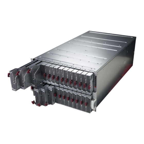
Chapter 1: Introduction 1.2 Models and Features 6U Enclosures 6U enclosures house up to 28 MicroBlade servers. The maximum may vary depending on the CPU wattages. 6U Enclosure Capabilities Power Supplies Manage Model Switch Options Options MBE-628E-422 Four 2200W Four 2200W, or MBE-628EB-422 Two MBM-GEM-004, MBM-GEM-001, MBM-XEM-001, Four 1200W BBP... - Page 9 Chapter 1: Introduction LAN Port Status Indicators Console Port Figure 1-1. MBE-628E Front View Front Features Feature Description Status Green: All blades, switch modules, CMM, power supplies, and fans are operating normally. Indicators Red: Critical warning—some components or modules are not operating normally. LAN Port Network port for the blade system Console Port...
- Page 10 Chapter 1: Introduction Figure 1-2. MBE-628E-622 Rear View Rear Features Feature Description Six power supply modules with fans Two fans Two Chassis Management Modules (CMMs) Switches Note: For the following blade servers, all networking goes through the switch in the A1 slot (upper left slot) so the switch in the other slot will not work with the blade network: MBI- 6118D-T2/T4/T2H/T4H, MBI-6128R-T2/T2X, MBI-6118G-T41X and MBI-6218G-T41X blades.
-
Page 11: Enclosures
Chapter 1: Introduction 3U Enclosures 3U enclosures house up to 14 MicroBlade Intel processor based servers. The maximum may vary depending on the CPU wattages. 3U Enclosure Capabilities Model Power Supplies Managemnt GbE Switch/Pass-thru Module Options MBE-314E-422 Four 2200W Two MBM-GEM-004, MBM-XEM-002, MBM-XEM-002+, MBM-XEM-100, MBM-25G-P20 MBE-314E-222 Two 2200W... - Page 12 Chapter 1: Introduction Figure 1-4. MBE-314E-420 Rear View Rear Features Feature Description Four power supply modules with fans Chassis Control Module (CMM) Switches...
-
Page 13: Switches
VLAN, STP, 802.1AX, 802.1AB, one console port, one USB port Marvel BobCat3 Low Latency Switch MBM-XEM-100 56x 10Gbps Internal Ports; 4x 100Gbps/40Gbps (QSFP28) and 1x 1Gbps (RJ45) External Uplink Ports VLAN, STP, 802.1AX, 802.1AB, one console port MBM-25G-P20 Supermicro Pass-thru Switch These modules are described in a separate manual. -
Page 14: Chapter 2 Installation Into A Rack
Chapter 2: Installation into a Rack Chapter 2 Installation into a Rack 2.1 Overview This chapter provides advice and instructions for mounting your system in a server rack. 2.2 Unpacking the System Inspect the box in which the enclosure was shipped, and note if it was damaged. If so, file a claim with the carrier. -
Page 15: Rack Precautions
Chapter 2: Installation into a Rack Rack Precautions • Ensure that the leveling jacks on the bottom of the rack are extended to the floor so that the full weight of the rack rests on them. • In single rack installations, stabilizers should be attached to the rack. In multiple rack in- stallations, the racks should be coupled together. -
Page 16: Circuit Overloading
Chapter 2: Installation into a Rack Circuit Overloading Consideration should be given to the connection of the equipment to the power supply circuitry and the effect that any possible overloading of circuits might have on overcurrent protection and power supply wiring. Appropriate consideration of equipment nameplate ratings should be used when addressing this concern. -
Page 17: Installing The Enclosure
Chapter 2: Installation into a Rack 2.4 Installing the Enclosure There are a variety of rack units on the market, which may require a slightly different assembly procedure. Also see the instructions that came with the rails. This rail set fits a rack between 26.8"... - Page 18 Chapter 2: Installation into a Rack Figure 2-2. Securing the Left Rail to the Rack 3. Lift the enclosure and slide it into the rack. Use two roundhead screws on each side of the server to lock it into place. Figure 2-4.
-
Page 19: Chapter 3 Maintenance And Component Installation
Chapter 3: Maintenance and Component Installation Chapter 3 Maintenance and Component Installation This chapter provides instructions on installing and replacing main system components. To prevent compatibility issues, only use components that match the specifications and/or part numbers given. 3.1 Removing Power Use the following procedure to ensure that power has been removed from the system. -
Page 20: Installing Components
Chapter 3: Maintenance and Component Installation 3.2 Installing Components Install: • Power Supply Modules (details in Chapter 4) • Fans • • Switches or pass-thru modules • Blade servers In all cases, slide the component into the enclosure, then secure with the locking lever. Note: All module bays must be populated either with a module or a dummy module cover to maintain proper airflow. -
Page 21: Installing A Blade Unit Into The Enclosure
Chapter 3: Maintenance and Component Installation Installing a Blade Unit into the Enclosure See the manual for your MicroBlade server for full details on its installation and configuration. 1. Fully open the locking lever on the blade and slowly push it into its bay. 2. -
Page 22: Software Mode Selection
Chapter 3: Maintenance and Component Installation 3.3 Software Mode Selection Using the Web-based Management Utility, you can specify your MicroBlade system to use a different mode for quieter operation and lower fan speed. This is done by selecting a mode in the CMM Operation Mode section of the CMM Status screen. -
Page 23: Chapter 4 Power And Cooling
Chapter 4: Power Supplies and Fans Chapter 4 Power and Cooling The MicroBlade enclosure integrates a power supply and a cooling fan into a single module. The fan can operate independently from the power supply, so that if the power supply fails, the fan continues to provide cooling for the system. -
Page 24: Installing A Power Supply
Chapter 4: Power Supplies and Fans For details on the required power cord for your country, see the SuperMicro web site at: www.supermicro.com/products/superblade/powersupply/powercord.cfm 4.2 Installing a Power Supply To prevent compatibility issues, only use components that match the specifications or part numbers. -
Page 25: Removing A Power Supply
Chapter 4: Power Supplies and Fans Removing a Power Supply 1. Remove the power cord from the power supply unit. 2. Release the locking clip to unlock the power supply module. 3. Pull out the locking handle and remove the unit. To release the handle, squeeze the two metal plates of the handle with your thumb and fingers, and then pull the module out. -
Page 26: Power Management
Chapter 4: Power Supplies and Fans 4.4 Power Management The Chassis Management Module assumes the maximum power case for each blade prior to applying power. If the system power is not sufficient, the CMM will not allow that unit to power up. -
Page 27: Power Supply Specifications
Chapter 4: Power Supplies and Fans 4.6 Power Supply Specifications PWS-1K67P-1R Feature Description Maximum Output 1600W/1400W/1200W Type Hot-swap Redundant Module (N+1) Dimensions (WxLxH) 106.5 x 241.3 x 84 mm 100-120Vac input: 14.2 - 12A Input Rated Voltage/ 120-140Vac input: 13.7 - 11.7A Current 200-240Vac input: 9.4 - 7A Rated Frequency... - Page 28 Chapter 4: Power Supplies and Fans PWS-2K01A-BR Feature Description Maximum Output 2000W/1980W/1800W/1000W Type Hot-swap Redundant Module (N+1) Dimensions (WxLxH) 106.5 x 283.3 x 84 mm 100-127Vac input: 12 - 9.5A 200-220Vac input: 10 - 9.5A Input Rated Voltage/ 220-230Vac input: 10 - 9.5A Current 230-240Vac Input: 10 - 9.5A 200-240Vac Input: 11.8 - 9.6A (UL/cUL Only)
- Page 29 Chapter 4: Power Supplies and Fans PWS-2K21A-BR Feature Description Maximum Output 2200W Type Hot-swap Redundant Module (N+1) Dimensions (WxLxH) 106.5 x 245.3 x 84 mm 100-127Vac input: 100A 200-220Vac input: 150A Input Rated Voltage/ 220-230Vac input: 165A Current 230-240Vac Input: 174A 200-240Vac Input: 183.3A (UL/cUL Only) Rated Frequency 50-60HZ...
-
Page 30: Chapter 5 Chassis Management Module
Chapter 5: Chassis Management Module Chapter 5 Chassis Management Module The Chassis Management Module (CMM) is a "command” module that communicates with the blade units, the power supplies and the blade switches. Used in conjunction with the Web Interface or IPMI View management software, the CMM provides administrator control over individual blade units, power supplies, cooling fans and networking switches and monitors onboard temperatures, power status, voltage levels and fan speeds. - Page 31 Chapter 5: Chassis Management Module Reset USB Ports Ethernet Ports Serial Port Info LED Fault LED Power LED Locking Lever Figure 5-2. MBM-CMM-001 Module Interface MBM-CMM-001 Feature Description Management Can manage up to 28 blade units, network modules and eight power supplies Capabilities Ports Two Ethernet ports, one serial port and two USB ports (for debug only)
-
Page 32: Capabilities
Chapter 5: Chassis Management Module Capabilities The CMM provides a dedicated, local and remote KVM (keyboard/video/mouse) connection over an out of band TCP/IP Ethernet network during any server state (functioning, blue-screen, powered down, BIOS and so on). It also supports Virtual Media (VM) redirection for CD, floppy and USB mass storage devices and configures such information as the switch IP addresses. -
Page 33: Configuring The Cmm
Chapter 5: Chassis Management Module Removing the Module: 1. Pull out the release handle to the open position. 2. Pull the module out of the bay. 3. Replace immediately with another module or with a dummy module cover to maintain airflow integrity. -
Page 34: Configuring The Cmm In Windows Os
Chapter 5: Chassis Management Module Configuring the CMM in Windows OS: 1. Go to Start > Control Panel > Network Connections. 2. Right-click on LAN to View Properties. 3. On the General tab page, choose “Internet Protocol (TCP/IP)” and click Properties. Figure 5-3. - Page 35 Chapter 5: Chassis Management Module Figure 5-4. Configuring CMM, Choose Protocol Once the IP address for the computer system is configured, the CMM can be accessed through the web browser by entering the default IP address 192.168.100.100 of the CMM into the browser’s address bar.
-
Page 36: Cmm Functions
Chapter 5: Chassis Management Module Caution: Do not change any other setting, unless you are familiar with it. Note: The above screens are examples for purposes of demonstrating this procedure. The screens you actually view may or may not appear the same as those shown above. 5.4 CMM Functions The following sections describe local functions and remote functions of the CMM. -
Page 37: Monitoring Functions
Chapter 5: Chassis Management Module Monitoring Functions Used in conjunction with IPMI or the Web-based Management utility, the CMM module can monitor and provide information on the hardware health of the blade modules and the system as a whole. In addition to the monitoring functions, you can remotely power on, power off or reboot a system. -
Page 38: Firmware
The Web-based Management Utility is a web-based interface that consolidates and simplifies system management for Supermicro MicroBlade systems. The Web-based Management Utility aggregates and displays data from the CMM module. The Web-based Management Utility provides the following key management features: •... -
Page 39: Address Defaults
Login. The Web-based Management Utility Home Page will then display as shown below. Note: Supermicro ships standard products with a unique password for the BMC ADMIN user. This password can be found on a label on the motherboard. For more information, please refer to our website at https://www.supermicro.com/en/support/BMC_Unique_Password and https://... -
Page 40: Appendix A Standardized Warning Statements For Ac Systems
Supermicro's Technical Support department for assistance. Only certified technicians should attempt to install or configure components. Read this appendix in its entirety before installing or configuring components in the Supermicro chassis. These warnings may also be found on our website at www.supermicro.com/about/policies/... - Page 41 Appendix A: Warning Statements Warnung WICHTIGE SICHERHEITSHINWEISE Dieses Warnsymbol bedeutet Gefahr. Sie befinden sich in einer Situation, die zu Verletzungen führen kann. Machen Sie sich vor der Arbeit mit Geräten mit den Gefahren elektrischer Schaltungen und den üblichen Verfahren zur Vorbeugung vor Unfällen vertraut. Suchen Sie mit der am Ende jeder Warnung angegebenen Anweisungsnummer nach der jeweiligen Übersetzung in den übersetzten Sicherheitshinweisen, die zusammen mit diesem Gerät ausgeliefert wurden.
- Page 42 Appendix A: Warning Statements . ٌ ا ك ً ف حالة و ٌ يك أى تتسبب ف اصابة جسذ ة ٌ هذا الزهز ع ٌ خطز !تحذ ز قبل أى تعول عىل أي هعذات،يك عىل علن بالوخاطز ال ا ٌجوة عي الذوائز ٍ...
- Page 43 Appendix A: Warning Statements Warnung Vor dem Anschließen des Systems an die Stromquelle die Installationsanweisungen lesen. ¡Advertencia! Lea las instrucciones de instalación antes de conectar el sistema a la red de alimentación. Attention Avant de brancher le système sur la source d'alimentation, consulter les directives d'installation. .יש...
- Page 44 Appendix A: Warning Statements Warnung Dieses Produkt ist darauf angewiesen, dass im Gebäude ein Kurzschluss- bzw. Überstromschutz installiert ist. Stellen Sie sicher, dass der Nennwert der Schutzvorrichtung nicht mehr als: 250 V, 20 A beträgt. ¡Advertencia! Este equipo utiliza el sistema de protección contra cortocircuitos (o sobrecorrientes) del edificio.
- Page 45 Appendix A: Warning Statements Power Disconnection Warning Warning! The system must be disconnected from all sources of power and the power cord removed from the power supply module(s) before accessing the chassis interior to install or remove system components. 電源切断の警告 システムコンポーネントの取り付けまたは取り外しのために、...
- Page 46 Appendix A: Warning Statements אזהרה מפני ניתוק חשמלי !אזהרה יש לנתק את המערכת מכל מקורות החשמל ויש להסיר את כבל החשמלי מהספק .לפני גישה לחלק הפנימי של המארז לצורך התקנת או הסרת רכיבים يجب فصم اننظاو من جميع مصادر انطاقت وإ ز انت سهك انكهرباء من وحدة امداد انطاقت...
- Page 47 Appendix A: Warning Statements ¡Advertencia! Solamente el personal calificado debe instalar, reemplazar o utilizar este equipo. Attention Il est vivement recommandé de confier l'installation, le remplacement et la maintenance de ces équipements à des personnels qualifiés et expérimentés. !אזהרה .צוות מוסמך בלבד רשאי להתקין, להחליף את הציוד או לתת שירות עבור הציוד واملدربيه...
- Page 48 Appendix A: Warning Statements Warnung Diese Einheit ist zur Installation in Bereichen mit beschränktem Zutritt vorgesehen. Der Zutritt zu derartigen Bereichen ist nur mit einem Spezialwerkzeug, Schloss und Schlüssel oder einer sonstigen Sicherheitsvorkehrung möglich. ¡Advertencia! Esta unidad ha sido diseñada para instalación en áreas de acceso restringido. Sólo puede obtenerse acceso a una de estas áreas mediante la utilización de una herramienta especial, cerradura con llave u otro medio de seguridad.
- Page 49 Appendix A: Warning Statements Battery Handling Warning! There is the danger of explosion if the battery is replaced incorrectly. Replace the battery only with the same or equivalent type recommended by the manufacturer. Dispose of used batteries according to the manufacturer's instructions 電池の取り扱い...
- Page 50 Appendix A: Warning Statements هناك خطر من انفجار يف حالة اسحبذال البطارية بطريقة غري صحيحة فعليل اسحبذال البطارية فقط بنفس النىع أو ما يعادلها مام أوصث به الرشمة املصنعة جخلص من البطاريات املسحعملة وفقا لحعليامت الرشمة الصانعة 경고! 배터리가 올바르게 교체되지 않으면 폭발의 위험이 있습니다. 기존 배터리와 동일하거나 제 조사에서...
- Page 51 Appendix A: Warning Statements ¡Advertencia! Puede que esta unidad tenga más de una conexión para fuentes de alimentación. Para cortar por completo el suministro de energía, deben desconectarse todas las conexiones. Attention Cette unité peut avoir plus d'une connexion d'alimentation. Pour supprimer toute tension et tout courant électrique de l'unité, toutes les connexions d'alimentation doivent être débranchées.
- Page 52 Appendix A: Warning Statements Backplane Voltage Warning! Hazardous voltage or energy is present on the backplane when the system is operating. Use caution when servicing. バックプレーンの電圧 システムの稼働中は危険な電圧または電力が、 バックプレーン上にかかっています。 修理する際には注意く ださい。 警告 当系统正在进行时,背板上有很危险的电压或能量,进行维修时务必小心。 警告 當系統正在進行時,背板上有危險的電壓或能量,進行維修時務必小心。 Warnung Wenn das System in Betrieb ist, treten auf der Rückwandplatine gefährliche Spannungen oder Energien auf.
- Page 53 Appendix A: Warning Statements هناك خطز مه التيار الكهزبايئ أوالطاقة املىجىدة عىل اللىحة عندما يكىن النظام يعمل كه حذ ر ا عند خدمة هذا الجهاس 경고! 시스템이 동작 중일 때 후면판 (Backplane)에는 위험한 전압이나 에너지가 발생 합니다. 서비스 작업 시 주의하십시오. Waarschuwing Een gevaarlijke spanning of energie is aanwezig op de backplane wanneer het systeem in gebruik is.
- Page 54 Appendix A: Warning Statements תיאום חוקי החשמל הארצי !אזהרה .התקנת הציוד חייבת להיות תואמת לחוקי החשמל המקומיים והארציים تركيب املعدات الكهربائية يجب أن ميتثل للقىاويه املحلية والىطىية املتعلقة بالكهرباء 경고! 현 지역 및 국가의 전기 규정에 따라 장비를 설치해야 합니다. Waarschuwing Bij installatie van de apparatuur moet worden voldaan aan de lokale en nationale elektriciteitsvoorschriften.
- Page 55 Appendix A: Warning Statements Attention La mise au rebut ou le recyclage de ce produit sont généralement soumis à des lois et/ou directives de respect de l'environnement. Renseignez-vous auprès de l'organisme compétent. סילוק המוצר !אזהרה .סילוק סופי של מוצר זה חייב להיות בהתאם להנחיות וחוקי המדינה التخلص...
- Page 56 Appendix A: Warning Statements Warnung Gefährlich Bewegende Teile. Von den bewegenden Lüfterblätter fern halten. Die Lüfter drehen sich u. U. noch, wenn die Lüfterbaugruppe aus dem Chassis genommen wird. Halten Sie Finger, Schraubendreher und andere Gegenstände von den Öffnungen des Lüftergehäuses entfernt.
- Page 57 Verbindungskabeln, Stromkabeln und/oder Adapater, die Ihre örtlichen Sicherheitsstandards einhalten. Der Gebrauch von anderen Kabeln und Adapter können Fehlfunktionen oder Feuer verursachen. Die Richtlinien untersagen das Nutzen von UL oder CAS zertifizierten Kabeln (mit UL/CSA gekennzeichnet), an Geräten oder Produkten die nicht mit Supermicro gekennzeichnet sind.
- Page 58 .قيرح وأ لطع يف ببستي دق ىرخأ تالوحمو تالباك يأ مادختسا .ميلسلا سباقلاو لصوملا مجح لبق نم ةدمتعملا تالباكلا مادختسا تادعملاو ةيئابرهكلا ةزهجألل ةمالسلا نوناق رظحيUL وأCSA ( ةمالع لمحت يتلاوUL/CSA) لبق نم ةددحملاو ةينعملا تاجتنملا ريغ ىرخأ تادعم يأ عمSupermicro.
- Page 59 사항을 준수하여 제공되거나 지정된 연결 혹은 구매 케이블, 전원 케이블 및 AC 어댑터를 사용하십시오. 다른 케이블이나 어댑터를 사용하면 오작동이나 화재가 발생할 수 있습니다. 전기 용품 안전법은 UL 또는 CSA 인증 케이블 (코드에 UL / CSA가 표시된 케이블)을 Supermicro 가 지정한 제품 이외의 전기 장치에 사용하는 것을 금지합니다. Stroomkabel en AC-Adapter...
- Page 60 Appendix B: System Specifications Appendix B System Specifications Dimensions (HxWxD) MBE-628L: 10.43 x 17.67 x 32 in. (265 x 449 x 812 mm) MBE-628E-420 and -820: 10.43 x 17.67 x 36.1 in. (265 x 449 x 917 mm) MBE-628E-416, -816, and -622: 10.43 x 17.67 x 34.45 in. (265 x 449 x 875 mm) MBE-314E-416: 5.21"...
- Page 61 Appendix B: System Specifications Perchlorate Warning California Best Management Practices Regulations for Perchlorate Materials: This Perchlorate warning applies only to products containing CR (Manganese Dioxide) Lithium coin cells. “Perchlorate Material-special handling may apply. See www.dtsc.ca.gov/ hazardouswaste/perchlorate”...
Need help?
Do you have a question about the MicroBlade MBE-628E-422 and is the answer not in the manual?
Questions and answers