
Related Manuals for Supermicro SC846E1-R710B


Summary of Contents for Supermicro SC846E1-R710B
- Page 1 UPER ® SC846 CHASSIS SERIES SC846TQ-R900B SC846E1-R710B SC846E1-R900B SC846E2-R900B USER’S MANUAL 1.0d...
- Page 2 Please Note: For the most up-to-date version of this manual, please see our web site at www.supermicro.com. Super Micro Computer, Inc. ("Supermicro") reserves the right to make changes to the product described in this manual at any time and without notice. This product, including software, if any, and documentation may not, in whole or in part, be copied, photocopied, reproduced, translated or reduced to any medium or machine without prior written consent.
- Page 3 Preface Preface About This Manual This manual is written for professional system integrators and PC technicians. It provides information for the installation and use of the SC846 chassis. Installation and maintenance should be performed by experienced technicians only. This manual lists compatible parts available when this document was published. Al- ways refer to the our Web site for updates on supported parts and configurations.
-
Page 4: Manual Organization
SC846 Chassis Manual Manual Organization Chapter 1: Introduction The first chapter provides a checklist of the main components included with this chassis and describes the main features of the SC846 chassis. This chapter also includes contact information. Chapter 2: System Safety This chapter lists warnings, precautions, and system safety. - Page 5 Appendix C: SAS-846TQ Backplane Specifications This section contains detailed specifications on the backplane for the SC846TQ chassis systems. Additional information can be found on the Supermicro Web site at www.supermicro.com. Appendix D: SAS-846EL Backplane Specifications This section contains detailed specifications on the backplane for the SC846EL chassis systems.
-
Page 6: Table Of Contents
Chapter 1 Introduction Overview ......................1-1 Shipping List ....................1-1 Part Numbers ....................1-1 Where to get Replacement Components ............1-2 Contacting Supermicro ..................1-3 Returning Merchandise for Service..............1-4 Chapter 2 System Safety Overview ......................2-1 Warnings and Precautions ................2-1 Preparing for Setup .................. - Page 7 Preface 4-10 Changing the CD-ROM, DVD-ROM, or Floppy Drive and HDD trays ..4-19 4-11 Accessing the Backplane ................4-22 Chapter 5 Rack Installation Overview ......................5-1 Unpacking the System ..................5-1 Preparing for Setup ..................5-1 Choosing a Setup Location ................5-1 Rack Precautions ....................
- Page 8 SC846 Chassis Manual Notes viii...
-
Page 9: Chapter 1 Introduction
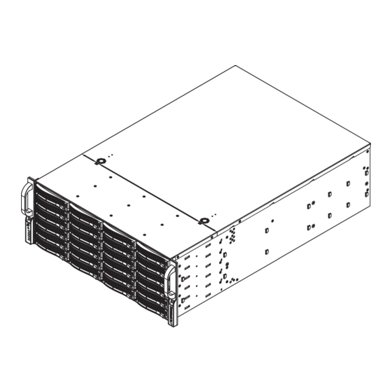
Chapter 1 Introduction Overview Supermicro’s SC846 4U chassis features a unique and highly-optimized design. The chassis is equipped with high efficiency power supply. High-performance fans provide ample optimized cooling for FB-DIMM memory modules and twenty-four hot-swappable drive bays offer maximum storage capacity. -
Page 10: Where To Get Replacement Components
Supermicro Authorized Distributors/ System Integrators/Resellers. A list of Supermicro Authorized Distributors/System Integrators/Resellers can be found at: http://www.supermicro.com. Click the Where to Buy link. -
Page 11: Contacting Supermicro
Super Micro Computer, Inc. 980 Rock Ave. San Jose, CA 95131 U.S.A. Tel: +1 (408) 503-8000 Fax: +1 (408) 503-8008 Email: marketing@supermicro.com (General Information) support@supermicro.com (Technical Support) Web Site: www.supermicro.com Europe Address: Super Micro Computer B.V. Het Sterrenbeeld 28, 5215 ML... -
Page 12: Returning Merchandise For Service
For faster service, RMA authorizations may be requested online (http://www. supermicro.com/support/rma/). Whenever possible, repack the chassis in the original Supermicro carton, using the original packaging material. If these are no longer available, be sure to pack the chassis securely, using packaging material to surround the chassis so that it does not shift within the carton and become damaged during shipping. -
Page 13: Chapter 2 System Safety
Chapter 2: System Safety Chapter 2 System Safety Overview This chapter provides a quick setup checklist to get your chassis up and running. Following the steps in order given should enable you to have your chassis setup and operational within a minimal amount of time. This quick set up assumes that you are an experienced technician, famailiar with common concepts and terminology. - Page 14 SC846 Chassis Manual • Be aware of the locations of the power on/off switch on the chassis as well as the room’s emergency power-off switch, disconnection switch or electrical outlet. If an electrical accident occurs, you can then quickly remove power from the system.
-
Page 15: General Safety Precautions
Chapter 2: System Safety General Safety Precautions • Keep the area around the chassis clean and free of clutter. • Place the chassis top cover and any system components that have been re- moved away from the system or on a table so that they won’t accidentally be stepped on. - Page 16 SC846 Chassis Manual • Handle a board by its edges only; do not touch its components, peripheral chips, memory modules or contacts. • When handling chips or modules, avoid touching their pins. • Put the serverboard and peripherals back into their antistatic bags when not in use.
-
Page 17: Chapter 3 System Interface
Chapter 3: System Interface Chapter 3 System Interface Overview There are several LEDs on the control panel as well as others on the drive carriers to keep you constantly informed of the overall status of the system as well as the activity and health of specific components. -
Page 18: Control Panel Buttons
SC846 Chassis Manual Control Panel Buttons There are two push-buttons located on the front of the chassis. These are (in order from left to right) a reset button and a power on/off button. Reset: The reset button is used to reboot the system. Power: The main power button is used to apply or remove power from the power supply to the server system. - Page 19 Chapter 3: System Interface NIC2: Indicates network activity on GLAN2 when flashing. NIC1: Indicates network activity on GLAN1 when flashing. HDD: Indicates IDE channel activity. SAS/SATA drive, and/or DVD-ROM drive activity when flashing. Power: Indicates power is being supplied to the system's power supply units. This LED should normally be illuminated when the system is operating.
-
Page 20: Drive Carrier Leds
SC846 Chassis Manual Drive Carrier LEDs Your chassis uses SAS/SATA. SAS/SATA Drives Each SAS/SATA drive carrier has two LEDs. • Green: Each Serial ATA drive carrier has a green LED. When illuminated, this green LED (on the front of the SAS/SATA drive carrier) indicates drive activity. A connection to the SAS/SATA backplane enables this LED to blink on and off when that particular drive is being accessed. -
Page 21: Chapter 4 Chassis Setup And Maintenance
Chapter 4: Chassis Setup and Maintenance Chapter 4 Chassis Setup and Maintenance Overview This chapter covers the steps required to install components and perform mainte- nance on the chassis. The only tool you will need to install components and perform maintenance is a Phillips screwdriver. -
Page 22: Removing The Chassis Cover
SC846 Chassis Manual Removing the Chassis Cover Remove this screw (if necessary) Release Tab Figure 4-1: Removing the Chassis Cover Removing the Chassis Cover Press the release tabs to remove the cover from the locked position. Press both tabs at the same time. Once the top cover is released from the locked position, slide the cover toward the rear of the chassis. -
Page 23: Installing Hard Drives
Chapter 4: Chassis Setup and Maintenance Installing Hard Drives Figure 4-2: Removing Hard Drive Removing Hard Drive Trays from the Chassis Press the release button on the drive tray. This extends the drive bay handle. Use the handle to pull the drive out of the chassis. - Page 24 SC846 Chassis Manual Dummy Drive Drive Tray Figure 4-3: Chassis Drive Tray The drives are mounted in drive trays to simplify their installation and removal from the chassis. These trays also help promote proper airflow for the drive bays. Warning: Except for short periods of time (swapping hard drives), do not operate the server with the hard drives empty.
- Page 25 Chapter 4: Chassis Setup and Maintenance SAS/SATA Hard Drive Drive Tray Figure 4-5: Installing the Hard Drive into the Tray Slide the hard drive into the tray with the printed circuit board side facing down. Carefully align the mounting holes in both the drive tray and the hard drive. Secure the hard drive to the tray using six screws.
-
Page 26: Installing The Motherboard
SC846 Chassis Manual Installing the Motherboard I/O Shield Figure 4-7: I/O Shield Placement I/O Shield The I/O shield holds the motherboard ports in place. Install the I/O shield before you install the motherboard. Installing the I/O Shield Review the documentation that came with your motherboard. Become familiar with component placement, requirements, and precautions. -
Page 27: Permanent And Optional Standoffs
Chapter 4: Chassis Setup and Maintenance Flat head Round h Round head Pan head Permanent and Optional Standoffs 6-32 x 5 mm M2.6 x 5 6-32 x 5 mm M3 x 5 mm [0.197] [0.19 [0.197] [0.197] Standoffs prevent short circuits by securing space between the motherboard and RAIL the chassis surface. - Page 28 SC846 Chassis Manual Figure 4-9: Motherboard Installation Lay the motherboard on the chassis aligning the permanent and optional standoffs Secure the motherboard to the chassis using the rounded, Phillips head screws. Secure the CPU(s), heatsinks, and other components to the motherboard as described in the motherboard documentation.
-
Page 29: Add-On Card/Expansion Slot Setup
Chapter 4: Chassis Setup and Maintenance Add-on Card/Expansion Slot Setup Your SC846 chassis includes I/O slots for add-on cards and expansion cards. Add-on/Expansion Card Slots Figure 4-11: Installing Add-on and Expansion Cards The SC846 chassis includes slots for add-on cards and expansion cards. Installing Add-on and Expansion Cards in the SC846 Chassis: Disconnect the power supply, lay the chassis on a flat surface, and open the chassis cover. -
Page 30: Installing The Air Shroud
SC846 Chassis Manual Installing the Air Shroud Figure 4-12: Air Shroud for SC846LP Chassis Air shrouds concentrate airflow to maximize fan efficiency. The SC846 chassis air shroud does not require screws to set up Installing the Air Shroud Confirm that your air shroud matches your chassis model. Each shroud is labeled SC846LP, SC846RC, or SC846U, Place air shroud in the chassis. -
Page 31: Checking The Server's Air Flow
Chapter 4: Chassis Setup and Maintenance Checking the Server's Air Flow Checking the Air Flow 1. Make sure there are no objects to obstruct airflow in and out of the server. In addition, if you are using a front bezel, make sure the bezel's filter is replaced periodically. -
Page 32: System Fans
SC846 Chassis Manual System Fans Three heavy duty fans provide cooling for the chassis. These fans circulate air through the chassis as a means of lowering the chassis internal temperature. Release Tab Release Tab Figure 4-13: Front System Fan Figure 4-14: Rear System Fan Replacing a System Fan 1. - Page 33 Chapter 4: Chassis Setup and Maintenance Figure 4-15: Placing the Front System Fan Figure 4-16: Placing the Rear System Fan 4-13...
-
Page 34: Power Supply
An illuminated green light indicates that the power supply is operating. Redundant power supplies are hot-swappable, and can be changed without pow- ering down the system. New units can be ordered directly from Supermicro (see contact information in the Preface). 4-14... - Page 35 Chapter 4: Chassis Setup and Maintenance Release Figure 4-17: Power Supply Release Tab Changing the Power Supply: If your chassis includes a redundant power supply (at least two power mod- ules), you can leave the server running and remove only one power supply. If your server has only one power supply, you must power down the server and unplug the power cord.
- Page 36 SC846 Chassis Manual Figure 4-18: Removing the Power Supply 3. Pull the power supply out using the handle provided. 4. Replace the failed power module with the same model. 5. Push the new power supply module into the power bay until you hear a click. 6.
-
Page 37: Changing The Power Distributor
Chapter 4: Chassis Setup and Maintenance Changing the Power Distributor Server chassis above 2U require a power distributor. The power distributor provides failover and power supply redundancy. In the unlikely event you must change the power distributor, do following: Changing the Power Distributor Power down the server and remove the plug from the wall socket or power strip. - Page 38 SC846 Chassis Manual Locate the power distributor between the power supply and the fan row. Remove the two screws securing the power distributor housing to the chassis wall Remove the three screws securing the power distributor to the housing. Gently pull the power distributor and houseing from the chassis. Carefully guide all the cables through the power distributor housing.
-
Page 39: Changing The Cd-Rom, Dvd-Rom, Or Floppy Drive And Hdd Trays
Chapter 4: Chassis Setup and Maintenance 4-10 Changing the CD-ROM, DVD-ROM, or Floppy Drive and HDD trays The SC846 chassis supports the following drive configuration options: Options Position A Position B Position C Option One Floppy, DVD or Not available Not available CD-ROM drive Option Two... - Page 40 SC846 Chassis Manual Figure 4-22: HDD Tray Unscrew the four screws (6-32) holding the drive into the HDD tray.and set them aside. These will be needed later to mount the replacement drive into the HDD tray. Lift the drive tray up and out of the chassis. Remove Tray from...
- Page 41 Chapter 4: Chassis Setup and Maintenance Figure 4-24: Replacement Drive and Tray Installed in the Chassis Note the locations of the CD-ROM and DVD-ROM and the space for floppy drives in the beginning of this section. Determine which configuration option to use in the chassis before continuing.
-
Page 42: 4-11 Accessing The Backplane
SC846 Chassis Manual 4-11 Accessing the Backplane The SC846 chassis backplane is located behind the hard drives and in front of the front system fans. In order to change jumper settings on the backplane, it may be necessary to remove the backplane from the chassis. Removing the Backplane Power down and unplug the system from any power source. - Page 43 Chapter 4: Chassis Setup and Maintenance Remove the four lower screws securing the backplane housing to the chassis floor and set these aside for later use. Remove Four Lower Screws Figure 4-26: Removing the Lower Backplane Housing Screws Gently ease the backplane up and out of the chassis. Lift the Backplane From the...
- Page 44 SC846 Chassis Manual Installing the Backplane Gently slide the backplane and its housing back into position in the chassis. Slide the Backplane into the Chassis Figure 4-28: Replacing the Backplane in the Chassis Replace the four lower screws which secure the backplane housing to the chassis floor.
- Page 45 Chapter 4: Chassis Setup and Maintenance Replace the three upper screws which secure the backplane housing to the chassis. Reconnect the cabling to the backplane. Replace the Three Upper Screws Figure 4-30: Replacing the Three Upper Screws 4-25...
- Page 46 SC846 Chassis Manual Notes 4-26...
-
Page 47: Chapter 5 Rack Installation
Chapter 5: Rack Installation Chapter 5 Rack Installation Overview This chapter provides a quick setup checklist to get your chassis up and running. Following these steps in the order given should enable you to have the system operational within a minimum amount of time. Unpacking the System You should inspect the box the chassis was shipped in and note if it was damaged in any way. -
Page 48: Rack Precautions
SC846 Chassis Manual Warnings and Precautions! • This product is for installation only in a Restricted Access Location (dedicated equipment rooms, service closets and the like). Rack Precautions • Ensure that the leveling jacks on the bottom of the rack are fully extended to the floor with the full weight of the rack resting on them. -
Page 49: Rack Mounting Considerations
Chapter 5: Rack Installation • Always keep the rack's front door and all panels and components on the servers closed when not servicing to maintain proper cooling. Rack Mounting Considerations Ambient Operating Temperature If installed in a closed or multi-unit rack assembly, the ambient operating tempera- ture of the rack environment may be greater than the ambient temperature of the room. -
Page 50: Rack Mounting Instructions
SC846 Chassis Manual Rack Mounting Instructions Rack Rails Assembly This section provides information on installing the SC846 chassis into a rack unit with the rails provided. There are a variety of rack units on the market, which may mean that the assembly procedure will differ slightly. You should also refer to the installation instructions that came with the rack unit you are using. -
Page 51: Installing The Inner Rails On The Chassis
Chapter 5: Rack Installation Figure 5-2: Installing the Rails Installing the Inner Rails on the Chassis Installing the Inner Rails Place the inner rails on the side of the chassis aligning the hooks of the chas- sis with the inner rail holes. Make sure the rail faces "outward" so that it will fit with the rack's mounting bracket. -
Page 52: Installing The Outer Rails Onto A Rack
SC846 Chassis Manual Secure to the Front of the Rack Secure to the Rear of the Rack Attach Outer Racks Together Figure 5-3: Assembling the Outer Rails Installing the Outer Rails onto a Rack Installing the Outer Rails Attach the short bracket to the outside of the long bracket. You must align the pins with the slides. - Page 53 Chapter 5: Rack Installation Figure 5-4: Installing the Outer Rails to the Server Rack...
- Page 54 SC846 Chassis Manual Figure 5-5: Installing the Rack Rails Installing the Chassis onto a Rack Installing the Chassis into a Rack: Confirm that chassis includes the inner rails (A) and rail extensions (B). Also, confirm that the outer rails (C) are installed on the rack. Line chassis rails (A and B) with the front of the rack rails (C).
-
Page 55: Appendix A Sc846 Cables And Hardware
2 each, regional power cords Set for 4 SATA cables. Length varied CBL-0180L SATA various to minimize airflow interference. CBL-0217L Cable 16-pin control panel converter cable SC846E1-R900B, SC846E2-R900B, SC846E1-R710B Part # Type Length Description Ribbon, 16 pin to 16 pin ribbon CBL-0087 20"... - Page 56 SC846 Chassis Manual A-3 Compatible Cables These cables are compatible with the SC846 Chassis. Alternate SAS/SATA Cables Some compatible motherboards have different connectors. If your motherboard has only one SAS connector that the SAS/SATA cables must share, use one of the following cables.
-
Page 57: Extending Power Cables
Appendix A: Chassis Cables Extending Power Cables Although Supermicro chassis are designed with to be efficient and cost-effective, some compatible motherboards have power connectors located in different areas. To use these motherboards you may have to extend the power cables to the mother boards. - Page 58 SC846 Chassis Manual A-4 Chassis Screws The accessory box includes all the screws needed to setup your chassis. This section lists and describes the most common screws used. Your chassis may not require all the parts listed. HARD DRIVE Flat head Pan head 6-32 x 5 mm 6-32 x 5 mm...
-
Page 59: Appendix B Sc846 Power Supply Specifications
50 - 60Hz 3 - 4 Amp +5V standby 4 Amp +12V 75 Amp +5V 50 Amp +3.3V 30 Amp -12V 0.6 Amp SC846E1-R710B 710W MFR Part # PWS-711-1R DC Input Voltage Range = -36V to -75V (24A - 11A) Voltage... - Page 60 SC846 Chassis Manual Notes...
-
Page 61: Appendix C Bpn-Sas-846Tq Backplane Specifications
Appendix C: BPN-SAS-846TQ Backplane Specifications Appendix C BPN-SAS-846TQ Backplane Specifications To avoid personal injury and property damage, carefully follow all the safety steps listed below when accessing your system or handling the components. C-1 ESD Safety Guidelines Electriostatic Discharge (ESD) can damage electronic com ponents. To prevent damage to your system, it is important to handle it very carefully. - Page 62 SC846 Chassis Manual C-3 A Note to Users • All images and layouts shown in this user's guide are based upon the latest PCB Revision available at the time of publishing. The card you have received may or may not look exactly the same as the graphics shown in this manual.
-
Page 63: Front Connectors
Appendix C: BPN-SAS-846TQ Backplane Specifications Jumper Settings and Pin Definitions C-4 Front Connectors and Jumpers Figure C-1: Front Connectors Front Connectors Chip: MG 9072 SideBand Connector #1 (JP66) Upgrade Connectors: JP69, JP78 and #2 (JP68) and JP115 SideBand Connector #3 (JP75) ACT_IN: JP26, JP47, and JP108 and #4 (JP77) C Connector #1 (JP37) and #2... - Page 64 SC846 Chassis Manual Figure C-2: SAS Ports SAS Port #0 J5 SAS Port #1 J14 SAS Port #2 J26 SAS Port #3 J40 SAS Port #4 J6 SAS Port #5 J16 SAS Port #6 J29 SAS Port #7 J41 SAS Port #8 J7 SAS Port #9 J22 SAS Port #10 J30 SAS Port #11 J42...
- Page 65 Appendix C: BPN-SAS-846TQ Backplane Specifications C-5 Front Connector and Pin Definitions 1. MG9072 Chip The MG9072 is an enclosure management chip that supports the SES-2 controller and SES-2 protocols. 2. Upgrade Connectors The upgrade connectors are designated JP69, JP78, and JP115 and are used for manufactur- er's diagnostic purposes only.
- Page 66 SC846 Chassis Manual 7./8./9./ Sideband Headers Sideband Headers (JP66, JP68, JP75, JP77, The sideband headers are designated JP66, JP112 and JP114) JP68, JP75, JP77, JP112, and JP114. For Pin # Definition Pin # Definition SES-2 to work properly, you must connect an SGPIO: Controller ID SDIN...
- Page 67 Appendix C: BPN-SAS-846TQ Backplane Specifications C-6 Front Jumper Locations and Pin Definitions JP35 JP50 JP97 JP98 JP99 JP100 JP129 JP84 JP61 JP62 JP63 JP64 Figure C-3: Front Jumpers Explanation of Jumpers Connector To modify the operation of the backplane, Pins jumpers can be used to choose between optional settings.
-
Page 68: Jumper Settings
SC846 Chassis Manual Jumper Settings Jumper Jumper Settings Note 1-2: Reset MG 9072 Chip Reset #1 JP35 2-3: Default 1-2: Reset MG 9072 Chip Reset #2 JP50 2-3: Default 1-2: Reset MG 9072 Chip Reset #3 JP129 2-3: Default Fan Jumper Settings This backplane can use up to four fans. - Page 69 Appendix C: BPN-SAS-846TQ Backplane Specifications C and SGPIO Modes and Jumper Settings This backplane can utilize I C or SGPIO. SGPIO is the default mode and can be used without making changes to your jumper. The following information details which jumper must be configured to use SGPIO mode or restore your backplane to I C mode.
-
Page 70: Front Led Indicators
SC846 Chassis Manual Front LED Indicators D53 D54 D45 D47 D49 D51 D3 D36 D89 Figure C-4: Front LEDs Front Panel LEDs State Specification Failure in Fan #1 Failure in Fan #2 Failure in Fan #3 Failure in Fan #4 Alarm #1: Overheat/Drive Failure in Chan- nel 1 Alarm #2: Overheat/Drive Failure in Chan-... - Page 71 Appendix C: BPN-SAS-846TQ Backplane Specifications C-7 Rear Connectors and LED Indicators SAS #20 SAS #21 SAS #22 SAS #23 SAS #16 SAS #17 SAS #18 SAS #19 SAS #12 SAS #13 SAS #14 SAS #15 SAS #8 SAS #9 SAS #10 SAS #11 SAS #4 SAS #5...
- Page 72 SC846 Chassis Manual Rear LED Indicators Rear LED Indicators Rear LED Hard Drive Activity Failure LED SAS #0 SAS #1 SAS #2 SAS #3 D102 D107 SAS #4 SAS #5 SAS #6 SAS #7 D104 D108 SAS #8 SAS #9 SAS #10 SAS #11 D106...
-
Page 73: Appendix Dbpn-Sas-846El Backplane Specifications
Appendix D: BPN-SAS-846EL Backplane Specifications Appendix D BPN-SAS-846EL Backplane Specifications Safety Guidelines To avoid personal injury and property damage, carefully follow all the safety steps listed below when accessing your system or handling the compo- nents. D-1 ESD Safety Guidelines Electriostatic Discharge (ESD) can damage electronic com ponents. - Page 74 SC846 Chassis Manual D-3 An Important Note to Users • All images and layouts shown in this user's guide are based upon the latest PCB Revision available at the time of publishing. The card you have received may or may not look exactly the same as the graphics shown in this manual.
- Page 75 Appendix D: BPN-SAS-846EL Backplane Specifications Jumper Settings and Pin Definitions D-4 Front Connectors and Jumpers REMOTE_FAN_FAIL_SOCKET1 BUZZER_ENB1 OVERHEATFAIL1 FANFAIL1 SEC_J2 SEC_J1 SEC_J0 PRI_J2 PRI_J1 PRI_J0 SEC_I2C1 SEC_IPMI1 PRI_IPMI1 BUZZER1 PRI_I2C1 SAS846EL2 REV 1.01 BAR CODE DESIGNED IN USA SEC_EXP1 PRI_FLASH1 S_J1 SEC_FLASH1 P_J1...
- Page 76 SC846 Chassis Manual D-5 Front Connector and Pin Definitions 1 and 2. Primary and Secondary I C Con- C Connector nectors Pin Definitions (JP44 and JP45) The I C Connectors are used to monitor HDD Pin# Definition activity and status. See the table on the right Data for pin definitions.
- Page 77 Appendix D: BPN-SAS-846EL Backplane Specifications 7. Fan Connectors Fan Connectors The 3-pin connectors, designated FAN1, Pin# Definition FAN2, and FAN3, provide power to the Ground fans. See the table on the right for pin +12V definitions. Tachometer 8 - 13. SAS Ports The Primary and Secondary sets of SAS ports provide expander features including cascading and failover From right to left...
-
Page 78: Explanation Of Jumpers
SC846 Chassis Manual D-6 Front Jumper Locations and Pin Definitions BUZZER_ENB1 REMOTE_FAN_FAIL_SOCKET1 OVERHEATFAIL1 FANFAIL1 SEC_Mode1 REMOTE_FAN_FAIL_SOCKET1 BUZZER_ENB1 OVERHEATFAIL1 FANFAIL1 SEC_J2 SEC_J1 SEC_J0 PRI_J2 PRI_J1 PRI_J0 SEC_I2C1 SEC_IPMI1 PRI_IPMI1 BUZZER1 PRI_I2C1 SAS846EL2 REV 1.01 BAR CODE DESIGNED IN USA SEC_EXP1 S_J1 PRI_FLASH1 SEC_FLASH1 PRI_EXP1... - Page 79 Appendix D: BPN-SAS-846EL Backplane Specifications General Jumper Settings Jumper Jumper Settings Note Factory Setting PRI_MODE1 Do not change Factory Setting SEC_MODE1 Do not change Open: Disable BUZZER_ENB1 Buzzer Enable Closed: Enable Socket Settings Socket Socket Setting Note REMOTE_FAN_FAIL_ Front Panel Fan Fail indicator Connected SOCKET (Optional)
- Page 80 SC846 Chassis Manual D-7 Rear Connectors and LED Indicators SAS #5 SAS #11 SAS #23 SAS #17 SAS #4 SAS #10 SAS #22 SAS #16 SAS #3 SAS #9 SAS #21 SAS #15 SAS #2 SAS #20 SAS #8 SAS #14 SAS #1 SAS #13 SAS #7...
- Page 81 Appendix D: BPN-SAS-846EL Backplane Specifications Rear LED Indicators Rear LED Hard Drive Activity Failure LED SAS #0 ACT #0 FAIL #0 SAS #1 ACT #1 FAIL #1 SAS #2 ACT #2 FAIL #2 SAS #3 ACT #3 FAIL #3 SAS #4 ACT #4 FAIL #4 SAS #5...
-
Page 82: Single Ports
Appendix D: BPN-SAS-846EL Backplane Specifications Dual Port and Cascading Configurations D-8 Single and Dual Port Expanders Single Ports SAS-846EL1 backplanes have a single-port expander that access all 24 drives and supports cascading. Dual Ports SAS-846EL2 backplanes have dual-port expanders that access all 24 drives. These dual-port expanders support cascading, failover, and recovery. - Page 83 SC846 Chassis Manual D-9 Failover The SAS-846EL2 backplane has two expanders which allow effective failover and recovery. Single Host Bus Adapter SAS HBA In a single host bus configuration, the backplane connects to one Host Bus Adapter (HBA). PRI_J2 SEC_J2 PRI_J1 SEC_J0 SEC_J1...
- Page 84 This section describes the supported power card for the SAS-846 series backplane. For more information, see the PCC-JBPWR2 power card manual. This manual can be found at the http://www.supermicro.com or as an appendix in the SAS-846EL chassis manual. JBPWR2 REV 1.00...
- Page 85 SC846 Chassis Manual Connecting an Internal Host Bus Adapter to the Backplane The following section lists the most common cables used to connect the Host Bus Adapter (HBA) to the backplane. PRI_J2 SEC_J2 PRI_J1 SEC_J0 SEC_J1 PRI_J0 (Host Bus Adapter) Figure D-11: Single Internal Host Bus Adapter PRI_J2 SEC_J2...
- Page 86 Appendix D: BPN-SAS-846EL Backplane Specifications Cable Name: IPASS (mini SAS) TO IPASS (mini SAS) Part #: CBL-0108L-02 Length: 39 cm (15 inches) Part #: CBL-0109L-02 Length: 22 cm (9 inches) Part #: CBL-0110L-02 Length: 18 cm (7 inches) Description: This cable has an ipass (SFF-8087/mini-sas) connector (36 pins) at each end.
- Page 87 SC846 Chassis Manual Connecting an External Host Bus Adapter to the Backplane This backplane supports external Host Bus Adapters. In this configuration, the HBA and the backplane are in different physical chassis. This allows a JBOD (Just a Bunch Of Drives) configuration from an existing system. Single External Host Bus Adapter PRI_J2 SEC_J2...
- Page 88 Appendix D: BPN-SAS-846EL Backplane Specifications Supported External HBA to Backplane Cable Use the following cable if your external HBA has an InfiniBand connector. Figure D-14: SAS InfiniBand Cable (CBL-0200L) Cable Name: SAS InfiniBand to Mini SAS X4 1M cable, PBF Part #: CBL-0200L Length: 1 meter Description: This cable has an InfiniBand connector (SFF-8470) on one end and...
- Page 89 SC846 Chassis Manual Connecting Multiple Backplanes in a Single Channel Environment This section describes the cables used when cascading from a single HBA. These connections use CBL-0167L internal cables and CBL-0166L external cables. CBL-0167L with Single Port Assembly PRI_J2 SEC_J2 PRI_J1 SEC_J0 SEC_J1...
- Page 90 Appendix D: BPN-SAS-846EL Backplane Specifications Single HBA Configuration Cables Single Port Cable Assembly Figure D-16: Single Port Internal Cable (CBL-0167L) Cable Name: SAS EL2/EL1 Backplane Cable (Internal) with 2-port Cascading Cable, 68 cm Part #: CBL-0167L (SFF-8087 to SFF-8088 x1) Ports: Single Placement: Internal cable Description: Internal cable.
- Page 91 SC846 Chassis Manual Connecting Multiple Backplanes in a Dual Channel Environment This section describes the cables used when cascading from dual HBAs. These connections use CBL-0168L internal cables and CBL-0166L external cables. PRI_J2 SEC_J2 PRI_J1 SEC_J0 SEC_J1 PRI_J0 Cable 0168L Port B Expander 2 Port A Expander 1 with Single Port Assembly...
- Page 92 Appendix D: BPN-SAS-846EL Backplane Specifications Dual HBA Configuration Cables Dual Port Cable Assembly Figure D-19: Dual Port Internal Cable (CBL-0168L) Cable Name: SAS Dual-port Cable Assembly, 68/76cm Part #: CBL-0168L Placement: Internal cable Ports: Dual Description: Internal cascading cable. Connects the backplane to the Host Bus Adapter (HBA) or external port.
- Page 93 The first backplane in a cascaded system requires a motherboard and HBA. Other servers require a power control card with no motherboard and no HBA. For more information, see the SC846 Chassis Manual available at www.supermicro.com. SEC_J2 PRI_J2...
- Page 94 Appendix D: BPN-SAS-846EL Backplane Specifications Server System with Single SAS HBA The expanders allow horizontal branching. This configuration also applies to dual ports. PRI_J2 PRI_J2 SEC_J2 PRI_J1 SEC_J2 PRI_J1 SEC_J0 SEC_J1 SEC_J0 SEC_J1 PRI_J0 PRI_J0 Port A Expander 1 Port A Expander 1 Power Card Cable 0167L (internal cable)
- Page 95 SC846 Chassis Manual Dual SAS HBA and Cascaded Configuration PRI_J2 SEC_J2 PRI_J1 SEC_J0 SEC_J1 PRI_J0 Port A Expander 1 Port B Expander 2 Dual Port Cable Assembly Cable 0168L (internal cable) Cable 0166L (external cables) PRI_J2 SEC_J2 PRI_J1 SEC_J0 SEC_J1 PRI_J0 Port B Expander 2 Port A Expander 1...
- Page 96 Appendix D: BPN-SAS-846EL Backplane Specifications Dual SAS HBA and Cascaded Configuration with Branching Port B Ex. 2 Port A Ex. 1 Port B Ex. 2 Port A Ex. 1 Power Card Port B Ex. 2 Port A Ex. 1 Port B Ex. 2 Port A Ex. 1 Power Power Card...
- Page 97 SC846 Chassis Manual Disclaimer (cont.) The products sold by Supermicro are not intended for and will not be used in life sup- port systems, medical equipment, nuclear facilities or systems, aircraft, aircraft devices, aircraft/emergency communication devices or other critical systems whose failure to per- form be reasonably expected to result in significant injury or loss of life or catastrophic property damage.
Need help?
Do you have a question about the SC846E1-R710B and is the answer not in the manual?
Questions and answers