Table of Contents
Advertisement
Quick Links
Advertisement
Table of Contents

Related Manuals for Supermicro SC946ED-R2KJBOD


Summary of Contents for Supermicro SC946ED-R2KJBOD
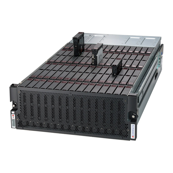
- Page 1 SC946ED 4U 90 BAY HYPER SCALE STORAGE ENCLOSURE SC946ED-R2KJBOD USER’S MANUAL...
- Page 2 This product, including software and documentation, is the property of Supermicro and/or its licensors, and is supplied only under a license. Any use or reproduction of this product is not allowed, except as expressly permitted by the terms of said license.
- Page 3 Preface Preface About This Manual This manual is written for professional system integrators and PC technicians. It provides information for the installation and use of the SC946ED storage enclosure. Installation and maintenance should be performed by experienced technicians only. This manual lists compatible parts available when this document was published. Always refer to the our website for updates on supported parts and configurations.
- Page 4 SC946ED Storage Enclosure Manual Manual Organization Chapter 1 Introduction The first chapter provides a checklist of the main components included with this chassis and describes the main features of the SC946ED storage enclosure. This chapter also includes contact information. Chapter 2 Standardized Warning Statements for AC/DC Systems This chapter lists warnings, precautions, and system safety.
- Page 5 Appendix A Power Supply Specifications This chapter lists the specifications of the power supply provided with your chas- sis. For additional information, refer to the Supermicro website at www.supermicro. com. Appendix B Backplane System Configuration This appendix provides details on the backplanes, midplane, power distributor board and expander boards included with the SC946ED chassis.
-
Page 6: Table Of Contents
Chapter 1 Introduction Overview ......................1-1 Shipping List ....................1-1 Where to get Replacement Components ............1-2 Contacting Supermicro ..................1-3 Returning Merchandise for Service..............1-4 Chapter 2 Standardized Warning Statements for AC Systems About Standardized Warning Statements ............2-1 Warning Definition ................... - Page 7 Preface Opening and Closing the Chassis Cover ............4-3 Chassis Cover ....................4-3 Front Panel Removal and Installation ............. 4-4 Front Panel Removal and Installation ............. 4-4 Installing Hot-Swappable 3.5" Hard Drives ............. 4-5 Accessing the Backplane Tray ................ 4-7 Expander Module Removal and Installation ...........
- Page 8 SC946ED Storage Enclosure Manual Notes viii...
-
Page 9: Chapter 1 Introduction
80 mm high-speed, low-vibration, hot-swappable cooling fans, the SC946ED is a reliable and hassle-free maintenance storage system. Shipping List Please visit the Supermicro website for the latest shiping lists and part numbers for your particular chassis model at www.supermicro.com. SC946ED Chassis... -
Page 10: Where To Get Replacement Components
Supermicro Authorized Distributors/System Integrators/Resellers. A list of Supermicro Authorized Distributors/System Integra- tors/Resellers can be found at: www.supermicro.com. Click the Where to Buy link. -
Page 11: Contacting Supermicro
Super Micro Computer, Inc. 980 Rock Ave. San Jose, CA 95131 U.S.A. Tel: +1 (408) 503-8000 Fax: +1 (408) 503-8008 Email: marketing@supermicro.com (General Information) support@supermicro.com (Technical Support) Website: www.supermicro.com Europe Address: Super Micro Computer B.V. Het Sterrenbeeld 28, 5215 ML... -
Page 12: Returning Merchandise For Service
For faster service, RMA authorizations may be requested online (http://www. supermicro.com/support/rma/). Whenever possible, repack the chassis in the original Supermicro carton, using the original packaging material. If these are no longer available, be sure to pack the chassis securely, using packaging material to surround the chassis so that it does not shift within the carton and become damaged during shipping. -
Page 13: Chapter 2 Standardized Warning Statements For Ac Systems
Only certified technicians should attempt to install or configure components. Read this appendix in its entirety before installing or configuring components in the Supermicro chassis. These warnings may also be found on our web site at http://www.supermicro.com/ about/policies/safety_information.cfm. Warning Definition Warning! This warning symbol means danger. - Page 14 SC946ED Chassis User's Manual Warnung WICHTIGE SICHERHEITSHINWEISE Dieses Warnsymbol bedeutet Gefahr. Sie befinden sich in einer Situation, die zu Verletzungen führen kann. Machen Sie sich vor der Arbeit mit Geräten mit den Gefahren elektrischer Schaltungen und den üblichen Verfahren zur Vorbeugung vor Unfällen vertraut.
- Page 15 Warning Statements for AC Systems جسذٌة اصابة ًتتسبب ف حالة ٌوكي أى ًاًك ف خطز ًٌٌع هذا الزهز !تحذٌز الذوائز بالوخاطز الٌاجوة عي ي على علن ، ك هعذات تعول على أي قبل أى الكهزبائٍة حىادث أي وقىع وٌع ل الىقائٍة...
-
Page 16: Installation Instructions
SC946ED Chassis User's Manual Installation Instructions Warning! Read the installation instructions before connecting the system to the power source. 設置手順書 システムを電源に接続する前に、 設置手順書をお読み下さい。 警告 将此系统连接电源前,请先阅读安装说明。 警告 將系統與電源連接前,請先閱讀安裝說明。 Warnung Vor dem Anschließen des Systems an die Stromquelle die Installationsanweisungen lesen. ¡Advertencia! Lea las instrucciones de instalación antes de conectar el sistema a la red de alimentación. -
Page 17: Circuit Breaker
Chapter 2: Warning Statements for AC Systems Circuit Breaker Warning! This product relies on the building's installation for short-circuit (overcurrent) protection. Ensure that the protective device is rated not greater than: 250 V, 20 A. サーキッ ト ・ ブレーカー この製品は、 短絡 (過電流) 保護装置がある建物での設置を前提としています。 保護装置の定格が250 V、... -
Page 18: Power Disconnection Warning
SC946ED Chassis User's Manual 경고! 이 제품은 전원의 단락(과전류)방지에 대해서 전적으로 건물의 관련 설비에 의존합니다. 보호장치의 정격이 반드시 250V(볼트), 20A(암페어)를 초과하지 않도록 해야 합니다. Waarschuwing Dit product is afhankelijk van de kortsluitbeveiliging (overspanning) van uw electrische installatie. Controleer of het beveiligde aparaat niet groter gedimensioneerd is dan 220V, 20A. - Page 19 Chapter 2: Warning Statements for AC Systems ¡Advertencia! El sistema debe ser disconnected de todas las fuentes de energía y del cable eléctrico quitado de los módulos de fuente de alimentación antes de tener acceso el interior del chasis para instalar o para quitar componentes de sistema. Attention Le système doit être débranché...
-
Page 20: Equipment Installation
SC946ED Chassis User's Manual Equipment Installation Warning! Only trained and qualified personnel should be allowed to install, replace, or service this equipment. 機器の設置 トレーニングを受け認定された人だけがこの装置の設置、 交換、 またはサービスを許可 されています。 警告 只有经过培训且具有资格的人员才能进行此设备的安装、更换和维修。 警告 只有經過受訓且具資格人員才可安裝、更換與維修此設備。 Warnung Das Installieren, Ersetzen oder Bedienen dieser Ausrüstung sollte nur geschultem, qualifiziertem Personal gestattet werden. -
Page 21: Restricted Area
Chapter 2: Warning Statements for AC Systems Waarschuwing Deze apparatuur mag alleen worden geïnstalleerd, vervangen of hersteld door geschoold en gekwalificeerd personeel. Restricted Area Warning! This unit is intended for installation in restricted access areas. A restricted access area can be accessed only through the use of a special tool, lock and key, or other means of security. -
Page 22: Battery Handling
SC946ED Chassis User's Manual אזור עם גישה מוגבלת !אזהרה יש להתקין את היחידה באזורים שיש בהם הגבלת גישה. הגישה ניתנת בעזרת .)'כלי אבטחה בלבד (מפתח, מנעול וכד محظورة مناطق ٍنتركُبها ف هذه انىحذة تخصيص تم ،أداة خاصت من خالل استخذاو فقط... - Page 23 Chapter 2: Warning Statements for AC Systems Warnung Bei Einsetzen einer falschen Batterie besteht Explosionsgefahr. Ersetzen Sie die Batterie nur durch den gleichen oder vom Hersteller empfohlenen Batterietyp. Entsorgen Sie die benutzten Batterien nach den Anweisungen des Herstellers. Attention Danger d'explosion si la pile n'est pas remplacée correctement. Ne la remplacer que par une pile de type semblable ou équivalent, recommandée par le fabricant.
-
Page 24: Redundant Power Supplies
SC946ED Chassis User's Manual Redundant Power Supplies Warning! This unit might have more than one power supply connection. All connections must be removed to de-energize the unit. 冗長電源装置 このユニッ トは複数の電源装置が接続されている場合があります。 ユニッ トの電源を切るためには、 すべての接続を取り外さなければなりません。 警告 此部件连接的电源可能不止一个,必须将所有电源断开才能停止给该部件供电。 警告 此裝置連接的電源可能不只一個,必須切斷所有電源才能停止對該裝置的供電。 Warnung Dieses Gerät kann mehr als eine Stromzufuhr haben. Um sicherzustellen, dass der Einheit kein trom zugeführt wird, müssen alle Verbindungen entfernt werden. -
Page 25: Backplane Voltage
Chapter 2: Warning Statements for AC Systems امداد الطاقة بوحدات عدة اتصاالت جهاز ال يكون لهذا قد الكهرباء عن وحدة ال لعسل كافة االتصاالت يجب إزالة 경고! 이 장치에는 한 개 이상의 전원 공급 단자가 연결되어 있을 수 있습니다. 이 장치에 전원을... -
Page 26: Comply With Local And National Electrical Codes
SC946ED Chassis User's Manual מתח בפנל האחורי !הרה אז קיימת סכנת מתח בפנל האחורי בזמן תפעול המערכת. יש להיזהר במהלך .העבודה اللىحة أوالطاقة المىجىدة على التيار الكهزبائي مه خطز هناك هذا الجهاس خدمة كه حذرا عند يعمل النظام عندما يكىن 경고! 시스템이... -
Page 27: Product Disposal
Chapter 2: Warning Statements for AC Systems Attention L'équipement doit être installé conformément aux normes électriques nationales et locales. תיאום חוקי החשמל הארצי !אזהרה הציוד חייבת להיות תואמת לחוקי החשמל המקומיים והארציים התקנת المتعلقة المحلية والىطىية قىاويه يجب أن يمتثل لل الكهربائية... -
Page 28: Hot Swap Fan Warning
SC946ED Chassis User's Manual ¡Advertencia! Al deshacerse por completo de este producto debe seguir todas las leyes y reglamentos nacionales. Attention La mise au rebut ou le recyclage de ce produit sont généralement soumis à des lois et/ou directives de respect de l'environnement. Renseignez-vous auprès de l'organisme compétent. - Page 29 Chapter 2: Warning Statements for AC Systems 警告 當您從機架移除風扇裝置,風扇可能仍在轉動。小心不要將手指、螺絲起子和其他 物品太靠近風扇。 Warnung Die Lüfter drehen sich u. U. noch, wenn die Lüfterbaugruppe aus dem Chassis genommen wird. Halten Sie Finger, Schraubendreher und andere Gegenstände von den Öffnungen des Lüftergehäuses entfernt. ¡Advertencia! Los ventiladores podran dar vuelta cuando usted quite ell montaje del ventilador del chasis.
-
Page 30: Power Cable And Ac Adapter
Electrical Appliance and Material Safety Law prohibits the use of UL or CSA -certified cables (that have UL/CSA shown on the code) for any other electrical devices than products designated by Supermicro only. 電源コードとACアダプター 製品を設置する場合、 提供または指定された接続ケーブル、 電源コードとACアダプター... - Page 31 Appareils électroménagers et de loi sur la sécurité Matériel interdit l'utilisation de UL ou CSA câbles certifiés qui ont UL ou CSA indiqué sur le code pour tous les autres appareils électriques que les produits désignés par Supermicro seulement.
- Page 32 SC946ED Chassis User's Manual Notes 2-20...
-
Page 33: Chapter 3 System Interface
Chapter 3 System Interface Chapter 3 System Interface Overview There are several LEDs on the control panel as well as others on the drive carriers to keep you constantly informed of the overall status of the system as well as the activity and health of specific components. -
Page 34: Control Panel Buttons
SC946ED Chassis Manual Control Panel Buttons There are two push-buttons located on the left handle of the chassis. These are (in order from top to bottom) a power on/off button and a reset button. Power: The main power button is used to apply or remove power from the power supply to the server system. - Page 35 Chapter 3 System Interface NIC1: Indicates network activity on the primary expander when flashing. NIC2: Indicates network activity on the secondary expander when flashing. Information LED: Informational LED Status Description An overheat condition has occured. Solid red (This may be caused by cable congestion). Fan failure, check for an inoperative fan.
-
Page 36: Drive Carrier Leds
SC946ED Chassis Manual Drive Carrier LEDs The SC946EDJ chassis uses SAS or SATA drives. SAS3 Drives Each SAS3 drive carrier has two sets of LEDs, one set of blue and red LED indica- tors for each drive. The LEDs function as follows: Blue Drive Carrier LED Indicator Color Status... -
Page 37: Rear Chassis Leds, Connectors And Components
Chapter 3 System Interface Rear Chassis LEDs, Connectors and Components The SC946ED features LEDs, connectors and other components on the rear of the chassis. These enabling you to interface with the system. See the illustration below for LED, connector and component identification. See the table below for descrip- tions of the module status indicator LEDs Power Power... - Page 38 SC946ED Chassis Manual Notes...
-
Page 39: Chapter 4 Chassis Setup And Maintenance
Chapter 4 Chassis Setup and Maintenance Chapter 4 Chassis Setup and Maintenance Overview This chapter covers the steps required to install components and perform mainte- nance on the chassis. The only tool you will need to install components and perform maintenance is a Phillips screwdriver. -
Page 40: Powering Up And Shutting Down The System
SC946ED Chassis Manual Powering Up and Shutting Down the System The procedures for powering up and shutting down the SC946ED differ slightly from typical systems. It is important to become familiar with the procedure and to follow it each time that the system is powered up or shut down. Powering Up the System First Time or Power Loss Power Up Procedure If powering up your system for the first time or after a loss of power, wait until the... -
Page 41: Opening And Closing The Chassis Cover
Chapter 4 Chassis Setup and Maintenance Opening and Closing the Chassis Cover Thumb Screw Thumb Figure 4-1. Opening the Chassis Cover Chassis Cover Opening the Chassis Cover 1. Release the two thumb screws on the right side of the chassis. 2. -
Page 42: Front Panel Removal And Installation
SC946ED Chassis Manual Front Panel Removal and Installation Remove Three Lower Front Screws Remove Four Front Screws Figure 4-2. Removing the Front Panel The SC946ED features a front panel which must be removed before pulling out the backplane tray. Front Panel Removal and Installation Removing the Front Panel 1. -
Page 43: Installing Hot-Swappable 3.5" Hard Drives
Chapter 4 Chassis Setup and Maintenance Installing Hot-Swappable 3.5" Hard Drives Drive Carrier Handle Figure 4-3. Removing a 3.5" Hard Drive Carrier The SC946ED chassis supports ninety 3.5" hard drives in tooless hard drive carriers to simplify their removal from the chassis. These carriers also help promote proper airflow through the chassis. - Page 44 Figure 4-5. Installing the Hard Drives and Carrier into the Chassis Warning! Enterprise level hard disk drives are recommended for use in Supermicro chassis and servers. For information on recommended HDDs, visit the Supermicro...
-
Page 45: Accessing The Backplane Tray
Replacement backplane trays are availble from Supermicro. For additional information, see Appendices B and C of this manual.+ Opening the Backplane Tray 1. - Page 46 Pull the back- plane tray all the way out if you are removing and replacing the backplane tray. 9. Check the cabling as directed by Supermicro Technical Support or return the entire backplane tray to Supermicro. Closing the Backplane Tray 1.
-
Page 47: Expander Module Removal And Installation
Chapter 4 Chassis Setup and Maintenance Expander Module Removal and Installation The SC946ED includes expanders which are contained in dual SAS3 modules at the rear of the chassis. The modules are hot-swappable and can be removed from the chassis without powering down the system. Each of these modules features four Mini SAS HD ports. -
Page 48: Expander Module Installation
SC946ED Chassis Manual Figure 4-11. Installing the Expander Module into the Chassis Expander Module Installation Installing the Expander Module 1. Align the expander module with the empty expander module bay. 2. Using the expander module handle, insert the expander module to the ex- pander module bay that it was removed from. -
Page 49: System Fans
Chapter 4 Chassis Setup and Maintenance System Fans Five hot-swappable, heavy-duty rear mounted fans provide cooling for the chassis. These fans circulate air through the chassis thereby lowering the chassis internal temperature. The SC946ED system fans are hot-swappable and can be removed without powering down the system. -
Page 50: Power Supply
Redundant power supplies are hot-swappable, and can be changed without pow- ering down the system. New units can be ordered directly from Supermicro (see contact information in the Preface). Release Tab Figure 4-14. -
Page 51: 4-10 Replacing The Power Distributor Board
Chapter 4 Chassis Setup and Maintenance 4-10 Replacing the Power Distributor Board The SC946ED chassis comes equipped with a PDB-PT946-S616 power distribu- tor. In the unlikely event that you need to replace the power distributor, use the following instructions. Changing the Power Distributor 1. - Page 52 SC946ED Chassis Manual Figure 4-15. Removing the Power Distributor Board 8. Remove the eight screws securing the power distributor board to the power distributor bracket and set them aside for later use. 9. Pull the power distributor board off the bracket. 10.
-
Page 53: 4-11 Assembling The Cable Management Arm
Chapter 4 Chassis Setup and Maintenance 4-11 Assembling the Cable Management Arm The SC946ED chassis supports a cable management arm (CMA) which helps to keep the chassis cables organized and clear of the rach and rail mechanisms. The swing arm functionality of the cable management arm keeps the cables clear while maintenance is being performed on the system. - Page 54 SC946ED Chassis Manual Remove the loop strap from the cable arm prior to use Figure 4-16. Removing the Loop Strap Prior to using the cable managment arm for the first time, remove the loop strap which secures the cable arm during transport. The loop strap is made of thin plas- tic which is easily removed with common household scissors.
- Page 55 Chapter 4 Chassis Setup and Maintenance CMA Connector #2 Apart CMA Connector #2 Assembled Figure 4-17. Installing the CMA Connector #1 onto the Inner Member 2. Install CMA connector #2 (C) onto CMA connector #2 base (D) on the inner member.
-
Page 56: Swing Arm Functionality Of The Cable Arm
SC946ED Chassis Manual Swing Arm Functionality of the Cable Arm Swing Arm Function (Swings Right) 1. Press the button on CMA connector #1 (A). 2. Pull back on CMA connector #1 to release it from the base. Figure 4-19. Swinging open the Cable Management Arm Swing Arm Function (Swings Left) 1. -
Page 57: Chapter 5 Rack Installation
Chapter 5: Rack Installation Chapter 5 Rack Installation Overview This chapter provides a quick setup checklist to get your chassis up and running. Following these steps in the order given should enable you to have the system operational within a minimal amount of time. Unpacking the System You should inspect the box which the chassis was shipped in and note if it was damaged in any way. -
Page 58: Warnings And Cautions
SC946ED Chassis Manual Warnings and Cautions Rack Precautions • Ensure that the leveling jacks on the bottom of the rack are fully extended to the floor with the full weight of the rack resting on them. • In single rack installations, stabilizers should be attached to the rack. •... -
Page 59: Rack Mounting Considerations
Chapter 5: Rack Installation Rack Mounting Considerations Ambient Operating Temperature If installed in a closed or multi-unit rack assembly, the ambient operating temperature of the rack environment may be greater than the ambient temperature of the room. Therefore, consideration should be given to installing the equipment in an environment compatible with the manufacturer’s maximum rated ambient temperature (TMRA). -
Page 60: Rack Mounting Instructions
SC946ED Chassis Manual Rack Mounting Instructions This section provides information on installing the chassis into a rack unit with the rails provided. There are a variety of rack units on the market, which may mean that the assembly procedure will differ slightly from the instructions provided. You should also refer to the installation instructions that came with the rack unit you are using. -
Page 61: Locking Tabs
Chapter 5: Rack Installation Locking Tabs Each inner rail has a locking tab. This tab locks the chassis into place when installed and pushed fully into the rack. These tabs also lock the chassis in place when fully extended from the rack. This prevents the server from coming completely out of the rack when when the chassis is pulled out for servicing. -
Page 62: Installing The Inner Rails On The Chassis
SC946ED Chassis Manual Inner Rails Figure 5-3. Installing the Inner Rails Figure 5-4. Inner Rails Installed on the Chassis Installing The Inner Rails on the Chassis Installing the Inner Rails 1. Remove the inner rail from the chassis accessory kit. Place the inner rail firmly against the side of the chassis, aligning the hooks on the side of the chassis with the holes in the inner rail. -
Page 63: Installing The Outer Rails On The Rack
Chapter 5: Rack Installation Figure 5-5. Extending and Releasing the Outer Rails Installing the Outer Rails on the Rack Installing the Outer Rails 1. Hang the hooks of the front of the outer rail onto the slots on the front of the rack. -
Page 64: Standard Chassis Installation
SC946ED Chassis Manual Figure 5-6. Installing into a Rack Note: Figures are for illustrative purposes. Always install servers from the bottom up. Standard Chassis Installation Installing the Chassis into a Rack 1. Confirm that the inner rails are properly installed on the chassis. 2. -
Page 65: Appendix A Sc946Ed Power Supply Specifications
Appendix A Power Supply Specifications Appendix A SC946ED Power Supply Specifications This appendix lists power supply specifications for your chassis system. SC946ED 1000W MFR Part # PWS-1K04A-1R 100-127 V, 50-60 Hz AC Input 200-240 V, 50-60 Hz Max: 66.7A (100Vac-127Vac) +12V Max: 83A (200Vac-240Vac) 12V SB... - Page 66 SC946ED Chassis Manual Notes...
-
Page 67: Appendix B Backplane System Configuration
Appendix B Backplane System Configuration Appendix B Backplane System Configuration B-1 Chassis Configuration The SC946ED chassis backplane system configuration consists of the following components: • Three backplanes, BPN-SAS3-946BA. • One midplane, BPN-SAS3-946MP. • One expander board, BPN-SAS3-946E90. • Two power distributor boards, PDB-PT946-616. BPN-SAS3-946E90 Expander Board (Contained in Removable Expander Board Modules) PDB-PT946-616 Power Distributor Board... - Page 68 SAS3-946MP Revision 1.0, expander board BPN-SAS3-946E90 Revision 1.0 and power distributor board PDB-PT946-616 Revision 1.0, the most current releases available at the time of publication. Always refer to the Supermicro web site at www.supermicro.com for the latest updates, compatible parts and supported configurations.
- Page 69 Appendix B Backplane System Configuration To avoid personal injury and property damage, carefully follow all the safety steps listed below when accessing your system or handling the components. B-3 ESD Safety Guidelines Electrostatic Discharge (ESD) can damage electronic com ponents. To prevent dam- age to your system, it is important to handle it very carefully.
- Page 70 SC946ED Chassis Manual Notes...
-
Page 71: Appendix C Cascading Configurations
Appendix C Cascading Configurations Appendix C Cascading Configurations Cascading Configuration Overview The SC946EDJ chassis backplanes can be configured in a variety of combinations for different applications. The following sections will provide cascading configuration options specific to your system. Cascading Configuration Options Single Host (LSI 9300-8E) with One JBOD HBA 9300-8E Primary Expander... - Page 72 SC946ED Chassis Manual Single Host (LSI 9300-8E) with Three JBODs HBA 9300-8E Primary Secondary Expander Expander Primary Secondary Expander Expander Primary Expander Secondary Expander Figure 5-3. Single Host (LSI 9300-8E) with Three JBODs Single Host (LSI 9300-16E) with One JBOD HBA 9300-16E Primary Expander Secondary Expander...
- Page 73 Appendix C Cascading Configurations Single Host (LSI 9300-16E) with Three JBODs HBA 9300-16E Primary Expander Secondary Expander Primary Expander Secondary Expander Primary Expander Secondary Expander Figure 5-6. Single Host (LSI 9300-8E) with Three JBODs Single Host (LSI 9300-16E) with One JBOD HBA 9300-8E HBA 9300-8E Primary Expander...
- Page 74 SC946ED Chassis Manual Dual Host (LSI 9300-8E) with Two JBODs HBA 9300-8E HBA 9300-8E Primary Secondary Expander Expander Primary Secondary Expander Expander Figure 5-9. Dual Host Cascading with Two JBODs Dual Host (LSI 9300-16E) with Two JBODs HBA 9300-16E HBA 9300-16E Primary Secondary Expander...
- Page 75 Appendix C Cascading Configurations Four Hosts (LSI 9300-8E) with One JBOD HBA 9300-8E HBA 9300-8E HBA 9300-8E HBA 9300-8E Primary Secondary Expander Expander Figure 5-10. Four Host Cascading with One JBOD Four Hosts (LSI 9300-8E) with One JBOD and Zoning HBA 9300-8E HBA 9300-8E HBA 9300-8E...
- Page 76 SC946ED Chassis Manual Disclaimer (cont.) The products sold by Supermicro are not intended for and will not be used in life sup- port systems, medical equipment, nuclear facilities or systems, aircraft, aircraft devices, aircraft/emergency communication devices or other critical systems whose failure to per- form be reasonably expected to result in significant injury or loss of life or catastrophic property damage.
Need help?
Do you have a question about the SC946ED-R2KJBOD and is the answer not in the manual?
Questions and answers