
Related Manuals for Allied Telesis AT-XEM-12S


Summary of Contents for Allied Telesis AT-XEM-12S
- Page 1 x900 Series Switch and SwitchBlade x908 ® Expansion Module Installation Guide XEM-1XP XEM-12S XEM-12T XEM-STK...
- Page 2 ® x900 Series Switch and SwitchBlade x908 Expansion Module Installation Guide XEM-1XP XEM-12S XEM-12T XEM-STK Download the complete document set from www.alliedtelesis.com/support/software...
- Page 3 Series Switch and SwitchBlade Document Number 613-000032 REV F © 2005-2007 Allied Telesis, Inc. All rights reserved. No part of this publication may be reproduced without prior written permission from Allied Telesis, Inc. Allied Telesis, Inc. reserves the right to change specifications and other information in this document without prior written notice.
-
Page 4: Table Of Contents
Installation Guide Contents About this Guide ... 4 Compatible Switches and Operating Systems ... 4 Package Contents ... 4 XEM-1XP 10Gigabit XFP Port ... 5 XEM-12S 100/1000BASE-X SFP Ports ... 7 XEM-12T 10/100/1000BASE-T RJ-45 Ports ... 9 XEM-STK Stacking Ports ... 10 Installation Procedure ... -
Page 5: About This Guide
Expansion Modules About this Guide Optional expansion modules (XEMs) enable economical combinations of port type, speed and density in a single switch. Front bays in the switch allow quick and easy installation. This Installation Guide describes how to install the following XEMs: ■... -
Page 6: Xem-1Xp 10Gigabit Xfp Port
XEM-1XP 10Gigabit XFP Port The XEM-1XP single-port 10Gigabit Ethernet expansion module features: ■ one XFP port ■ LEDs showing port status ■ 32MBytes of DDR SDRAM for packet buffering ■ support for hot-swappable XFP transceiver modules Front view XEM-1XP LINK The following LEDs report operations and faults on the XEM-1XP. - Page 7 The following XFP transceiver modules are approved for use with the XEM-1XP. Product No. AT-XPSR AT-XPLR AT-XPER40 For the latest list of approved XFP transceiver modules, contact your authorised Allied Telesis distributor or reseller. Media Type Description 10GBASE-SR 850nm short-haul transmission, 300m with MM fibre.
-
Page 8: Xem-12S 100/1000Base-X Sfp Ports
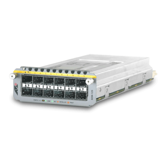
XEM-12S 100/1000BASE-X SFP Ports The XEM-12S 12-port 100/1000BASE-X expansion module features: ■ two rows of 6 SFP ports ■ LEDs showing port status ■ 32MBytes of DDR SDRAM for packet buffering ■ support for hot-swappable SFP transceiver modules ■ NEBS compliant Front view XEM-12S The following LEDs report operations and faults on the XEM-12S. - Page 9 1490, 1470, or 1310 1. Both ends of an individual fibre must use SFPs of a compatible wavelength. For the latest list of approved SFP transceiver modules, contact your authorised Allied Telesis distributor or reseller. Media Type Description 10/100/1000BASE-T Copper, 100m at 1000Mbps, RJ-45 connector.
-
Page 10: Xem-12T 10/100/1000Base-T Rj-45 Ports
XEM-12T 10/100/1000BASE-T RJ-45 Ports The XEM-12T 12-port RJ-45 expansion module features: ■ two rows of 6 RJ-45 ports ■ gigabit ports that support speeds of 10/100/1000Mbps ■ LEDs showing port status ■ 32MBytes of DDR SDRAM for packet buffering ■ cable fault detection and distance-to-fault diagnostics on switches running the AlliedWare operating system (see the Test Facility chapter in the Software Reference for the switch) -
Page 11: Xem-Stk Stacking Ports
Expansion Modules XEM-STK Stacking Ports The XEM-STK dual-port stacking expansion module features: ■ two 15Gbps full duplex stacking connections ■ LEDs showing port and stack member status ■ seven-segment stack ID display ■ recessed Select button to reset stack ID to 1 Front view XEM-STK STAT The following LEDs report operations and faults on the XEM-STK. - Page 12 Installation Guide A choice of 0.5m or 2.0m stacking cables can be ordered separately. For the latest list of approved cables, contact your authorised Allied Telesis distributor or reseller. The Select button resets the stack ID of this switch to 1, and causes the other members of the stack to be renumbered.
-
Page 13: Installation Procedure
■ Verify the package contents if you have not already done so. “Package Contents” on page contact your authorised Allied Telesis distributor or reseller. ■ Read the safety information for the switch. Safety information is available in the Installation and Safety Guide that is shipped with each switch. - Page 14 Installing or replacing XEMs without hot swap support Follow this procedure to: ■ install a XEM, except the XEM-STK, in a switch running the AlliedWare operating system ■ install a XEM-STK in a switch running the AlliedWare Plus operating system ■...
- Page 15 Expansion Modules Confirm there is no error message about installation in the log file and that the switch has recognised the XEM. On switches running the AlliedWare operating system, use the commands: show log show system On switches running the AlliedWare Plus operating system, use the commands: awplus>show system awplus>enable...
-
Page 16: Obtaining Documentation And Resources
You can download it from www.adobe.com. Other resources How-To Notes describe a range of standard Allied Telesis solutions, and include technical tips and guides to configuring specific hardware and software features. You can download the latest How-To Notes from www.alliedtelesis.com/resources/literature/howto.aspx. - Page 17 Contacting us With locations covering all of the established markets in North America, Latin America, Europe, Asia, and the Pacific, Allied Telesis provides localized sales and technical support worldwide. To find the representative nearest you, visit us on the Web at www.alliedtelesis.com.
Need help?
Do you have a question about the AT-XEM-12S and is the answer not in the manual?
Questions and answers