
Related Manuals for Alpha CXPS-C


Summary of Contents for Alpha CXPS-C
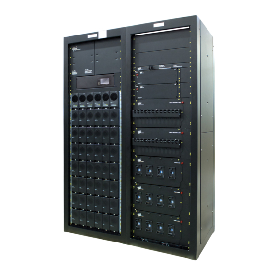
- Page 1 CXPS-C Centralized Power Plant Technical Guide 9400001-J1 Effective: 11/2018 Alpha Technologies Ltd.
- Page 3 Canada and USA: 1-888-462-7487 International: +1-604-436-5547 Copyright Copyright © 2018 Alpha Technologies Ltd. All rights reserved. Alpha is a registered trademark of Alpha Technolo- gies. No part of this documentation shall be reproduced, stored in a retrieval system, translated, transcribed, or transmit- ted in any form or by any means manual, electric, electronic, electromechanical, chemical, optical, or otherwise without prior explicit written permission from Alpha Technologies.
-
Page 5: Table Of Contents
Table of Contents 1. Safety ............................6 1.1 Safety Symbols .......................... 6 1.2 General Warnings and Cautions ....................6 1.3 Electrical Safety ......................... 7 1.4 Battery Safety ..........................7 2. Introduction ...........................8 2.1 Product Overview ........................8 2.2 Part Numbers and List Options ....................8 3. ... - Page 6 7.5 Connecting the Shunt and Inter-Bay Signal Cables ..............39 7.6 Mounting the Optional External Return Bar ................44 7.7 Battery Installation ........................45 7.8 Battery Maintenance Report ....................47 8. Wiring ..........................48 8.1 Installation Notes ........................48 8.2 Connecting the Frame and Reference Grounds ..............50 8.3 ...
- Page 7 List of Figures Figure 1 — CXPS-C Centralized Power Plant Basic System ............8 Figure 2 — Basic Power System ....................12 Figure 3 — Stand-alone Power Bay showing DC Charge Buses ........... 14 Figure 4 — Top View of Horizontal Inter-bay Busbars ..............14 Figure 5 ...
- Page 8 Figure 30 — Bolting Adjacent Bays Together ................. 36 Figure 31 — Example of Installed Inter-bay Buswork ..............38 Figure 32 — Shunt Connections ..................... 39 Figure 33 — Inter-bay Wiring Harness ................... 39 Figure 34 — CAN OUT Port Terminator ..................40 Figure 35 —...
-
Page 9: Safety
Keep it in a safe place. Review the drawings and illustrations contained in this manual before proceeding. If there are any questions regarding the safe installation or operation of this product, contact Alpha Technologies or the nearest Alpha representative. 1.1 Safety Symbols To reduce the risk of injury or death, and to ensure the continued safe operation of this product, the following sym- bols have been placed throughout this manual. -
Page 10: Electrical Safety
1.3 Electrical Safety WARNING! Hazardous voltages are present at the input of power systems. The DC output from rec- tifiers and batteries, though not dangerous in voltage, has a high short-circuit current capacity that may cause severe burns and electrical arcing. Before working with any live battery or power system, follow these precautions: a. -
Page 11: Introduction
2. Introduction 2.1 Product Overview The CXPS-C power system provides high capacity DC power for large communications applications—central offices, mobile switching centers, data center and cable headend facilities. The main source of power for the power system is commercial AC power, which is converted to DC by the modular switched mode rectifiers. It is a fully automatic system, which provides float and equalize capability for the batteries. -
Page 12: Specifications
3. Specifications Table A — Specifications for CXPS-C Power System Electrical DC Output Voltage AC Input Voltage 6 feeds: 4.0kW Rectifier Shelf 277/480Vac, 60Hz (3 Phase - 3 Wire + N + PE) 12kW Rectifier Shelf 480Vac, 60Hz (3 Phase - 3 Wire + PE) 8 feeds: 4.0kW Rectifier Shelf... - Page 13 Table B — Related Components Cordex HP 4kW rectifier See the Cordex HP 4kW rectifier datasheet for more detailed information. Cordex HP 12kW rectifier See the Cordex HP 12kW rectifier datasheet for more detailed information. System level alarms/controls Alarms/control parameters are user-programmable through built-in digital supervisory unit. See CXC HP datasheet for detailed information on alarms and controls. LCD with touch screen System OK (green LED) Indicators: System minor alarm (yellow LED)
- Page 14 Table D — Distribution, Busbars Number of negative landings Single power bay: 11 X 1/2" on 1 3/4" centers or 24 x 3/8" on 1" centers for batteries (rectifier side of Each additional power bay: 14 X 1/2" on 1 3/4" centers or 14 x 3/8" on 1" centers the shunt) Number of landings on the Single distribution bay: 14 X 1/2"...
-
Page 15: Features
4. Features The basic system consists of two bays and inter-bay copper busbarss. The power bay converts AC to fully regulated and filtered DC power, which is fed through a load shunt to the second bay for distribution. Basic power system •... -
Page 16: Power Bays
4.1.1 Cordex HP System Controller The Cordex HP system controller, mounted in the primary power bay, provides easy access to controls and display status. The controller provides comprehensive setup, control, monitoring and communication for Alpha DC power systems. Controller features include the following: •... -
Page 17: Figure 3 - Stand-Alone Power Bay Showing Dc Charge Buses
4.1.5 Power Bay DC Charge Buses FRONT Each standalone power bay has two vertical charge bars con- necting all return terminals and all negative terminals of the recti- fier shelves (Figure 3). These busbars are rated for the maximum current supplied by the rectifier shelves. In a multi-bay power system, the return vertical busbar connects to an inter-bay return bar located across the top of the power and distribution bays. -
Page 18: Rectifier Modules
4.2 Rectifier Modules The rectifier modules are "hot swappable" allowing for quick replacement and easy maintenance of the system. (They can be inserted or removed from the shelf without removing AC power or shutting down the entire system.) 4.2.1 Rectifier Alarms and LEDs Rectifier status, such as mains OK, Minor and Major alarms, display on the rectifier front panel. -
Page 19: Distribution Bays
4.3 Distribution Bays Distribution bays are designed for high capacity distribution applications. Each distribution bay can be equipped with a variety of different fuse/CB tier combinations, with or without LVLD option, as shown in Table E and Figure 7. Table E — Distribution Options per Bay Tier Type Rating Max Rating... -
Page 20: Figure 7 - Distribution Panel Options
LVD inhibit Bullet breaker tier High capacity breaker tier Distribution panel alarm indicator TPL fuse tiers Figure 7 — Distribution Panel Options 9400001-J1 Rev F... -
Page 21: Figure 8 - 4 Position Tpl
4.3.1 4 Position TPL Tier Features • Occupies 1 tier position • 2000A tier rating • Each position accepts max 800A TPL fuse • Current on each TPL is monitored via an 800A shunt • 2x landings per fuse 2 hole, 3/8" dia. on 1" center or 1/2" dia. on 1 3/4" center •... -
Page 22: Figure 10 - 6X 2 Position High Capacity Breaker
4.3.3 6x 2 Position high Capacity Breaker Tier Features • Occupies 1 tier positions • 2000A tier rating • Can accept 2P (300A-400A) high capacity breaker • Individually monitored by 800A Shunts • 2x landings per position 2 hole, 3/8" dia. on 1" center & 1/2" dia. on 1 3/4" center •... -
Page 23: Figure 12 - 3X 4 Position High Capacity Breaker
4.3.5 3x 4 Position high Capacity Breaker Tier Features • Occupies 1 tier positions • 2000A tier rating • Can accept 4P (800A) high capacity breaker • Individually monitored by 1000A Shunts • 2x landings per position 2 hole, 3/8" dia. on 1" center & 1/2" dia. on 1 3/4" center •... -
Page 24: Figure 14 - 2X 6 Position High Capacity Breaker
4.3.7 2x 6 Position high Capacity Breaker Tier Feature • Occupies 1 tier positions • 2000A tier rating • Can accept 6P (1200A) high capacity breaker • Individually monitored by 1500A Shunts • 2x landings per position 2 hole, 3/8" dia. on 1" center & 1/2" dia. on 1 3/4" center •... -
Page 25: Figure 16 - 18 Position Bullet Breaker
4.3.9 18 Position Bullet Breaker Tier Features • Occupies 1/2 tier positions • 600A tier rating • Can accept standard 1P (125A), 2P (200A), and 3P (300A) plug in breakers • Total shelf monitoring by 800A Shunt • 1P breaker/fuse (1 pole, 2 hole, 1/4" dia. on 5/8" center) •... -
Page 26: Figure 18 - Distribution Bay-Dc Distribution Bus
4.3.11 DC Distribution Buses Each distribution bay has a vertical distribution bus (see Figure 18) that brings power from the overhead busbars down into the bay. This bus is rated for 6000A continuous operation. Main vertical busbar LVD contactor (optional) Shunts Figure 18 —... -
Page 27: Figure 19 - Distribution Shunts
4.3.12 Distribution Shunts Each distribution panel has shunts (Figure 19) sized according to the breaker or fuse capacity. A shunt multiplexer panel, located in the top of the bay, monitors the individual branch load currents within the shelves of the individual distribution bay. The current measurements are sent to the controller, using CAN communi- cations, for data logging and display. -
Page 28: Dc Inter-Bay Copper
4.3.15 Distribution Panel Alarms Fuse/Breaker alarms occur when one or more fuse or breaker has opened. Each Breaker/Fuse panel is equipped with one alarm which is wired to the system controller. Indication is provided by a red lamp on each distribution panel (Figure 7). 4.4 DC Inter-bay Copper The inter-bay busbar is available in 4000A, 8000A and 12000A nominal sizing as required. -
Page 29: Figure 21 - External Battery Return Ground Bar
4.4.1 Live Bay Expansion Additional bays can be added to the system while online without shutting down the DC plant. 4.4.2 Internal Return Bar (Optional) The positive DC inter-bay common bar runs horizontally across the top of the distribution and power bays (within the bays). -
Page 30: Cordex Hp Controller
USB: dual ports, on each on the front and rear of the controller for upgrades and file management via a standard USB flash drive. • CAN: dual independent CAN bus ports for communication with the Alpha Cordex™ and AMPS family of products, which al- lows for a greater number of devices. •... -
Page 31: External Peripherals
The temperature sensor is provided by Alpha in various lengths. The input range for this signal is 0V to 5V and is powered internally from the L-ADIO. -
Page 32: Figure 25 - 6I-Adio Peripheral
LED Indication Each L-ADIO contains three LEDs for peripheral status indication. LVD – Yellow = LVD Override Engaged Power – Blue = Power present to device Comms – Green = L-ADIO has been acquired by the controller Front Panel Reset Button A reset button is located on the front panel. -
Page 33: Figure 26 - Redundant Input Power Module
4.6.3 Redundant Input Power Module The redundant input power module (RIPM) provides multiple power inputs to power the controller and any I/O peripherals such as the L-ADIO. The unit enables users to wire system power into the control devices from multiple locations (e.g., on battery and load side of LVD’s or A and B power system(s)) and provides Diode-or protection between power inputs. -
Page 34: Pre-Installation Preparation
5. Pre-Installation Preparation 5.1 Site Selection The power system must be mounted in a clean and dry environment. Consider both the floor loading and the physical space required for the CXPS-C power system and the batteries: • Dimensions for one bay: •... -
Page 35: Tools And Test Equipment
5.1.2 Installation component requirements Not Supplied • Concrete mounting hardware • AC electrical conduit, cable and fittings • External DC conduit, cable and fittings • Auxiliary frame (2" x 9/16") for optional external battery return busbar kit 5.2 Tools and Test Equipment Insulated tools are essential for a DC power system installation. -
Page 36: Inspection
6. Inspection 6.1 Packing Materials Alpha is committed to providing products and services that meet our customers’ needs and expectations in a sus- tainable manner, while complying with all relevant regulatory requirements. As such Alpha strives to follow our quality and environmental objectives from product supply and development through to the packaging for our products. -
Page 37: Frame Installation
7.1 Floor Drilling for Standard Anchoring NOTE: Earthquake anchoring is the type used in earthquake areas up to Zone 4. The CXPS-C power system frame is earthquake qualified when properly anchored to a 3000 psi (2.11 kg per sq. mm) concrete floor. -
Page 38: Placing And Securing The Bays
7.1.2 Setting the Anchors First, review manufacturer's instructions before setting the anchor. 1. Drop the anchor into the drilled hole. 2. Insert the anchor setting tool and hit it with a hammer to expand the anchor until the collar of the setting tool rests against the shoulder of the anchor. -
Page 39: Securing Adjacent Bays
7.3 Securing Adjacent Bays Locate the bay-to-bay bolting kits that ship with the equipment. Remove horizontal braces to make it easier to install horizontal busbars. Bolt each pair of bays to- gether. Remove the top flange at the front of the bay to access anchoring holes. -
Page 40: Installing The Inter-Bay Dc Bus Work Between Adjacent Frames
7.4 Installing the Inter-bay DC Bus Work between Adjacent Frames The inter-bay DC bus work ships as a kit that is sized according to the number of rectifiers and current demand of the load. In a new installation, the frame anchors should not have been set completely as per instructions in section 7.2.1. When adding a new frame to a working system, it may be necessary to loosen the floor anchors in the existing frame to permit final alignment. -
Page 41: Figure 31 - Example Of Installed Inter-Bay Buswork
Procedure 1. Assemble the inter-bay bus work with the bolts that ship in the kit with the copper buses. 2. Once assembled, torque all bolts to 75 ft/lbs. 3. Proceed with final setting of the bay floor anchors. Figure 31 — Example of Installed Inter-bay Buswork 9400001-J1 Rev F... -
Page 42: Connecting The Shunt And Inter-Bay Signal Cables
7.5 Connecting the Shunt and Inter-Bay Signal Cables This section applies to new installations as well as the installation of expansion distribution and power bays. 1. Locate the coils of cables that are tie- wrapped to the side of the power bay containing the controller. -
Page 43: Figure 34 - Can Out Port Terminator
7.5.1 Inter-bay CAN Bus Cables - Controller CAN bus connection provides a communication path between the controller and rectifiers, ADIO Shelf/Bay ID, and shunt mux(es) if installed. CAN bus cabling is sequentially daisy-chained from the controller to the components. Initial Installation: The CAN bus cabling, from the bottom shelf of the power bay to the top shelf, is factory installed and ready for con- nection to the next bay. -
Page 44: Figure 36 - Controller And Shelf/Bay Id, Can Bus And Shelf Id Cabling
CXC HP L-ADIO CAN IN CAN 1 CAN OUT CAN 2 (Terminated) Shelf/Bay ID Shelf/Bay ID Top rectifier shelf Top rectifier shelf CAN OUT CAN OUT Terminated Terminated Shelf ID Shelf ID CAN IN CAN IN Rectifier shelf Rectifier shelf CAN OUT CAN OUT Terminated Terminated Shelf ID Shelf ID CAN IN... -
Page 45: Figure 37 - Can Bus Termination 4.0Kw
Expanding and Existing System—CAN Bus Cables: NOTE: If your system has redundant rectifiers, it is recommended to power off the left most rectifier in the top shelf of the existing bay during this procedure. In your existing system, the CAN Bus is terminated at the highest shelf in the outermost power bay. (See Figure 35 for the sequence of CAN bus cabling) 1. -
Page 46: Figure 39 - Battery Disconnect Connections
7.5.2 LVBDs (purchased separately) If battery disconnect contactors are used: 1. Connect a secondary power source, from either side of the LVBD, to the controller. (Refer to "4.6.3 Redundant Input Power Module" on page 30) 2. Connect battery disconnect panels to the controller's battery fuse alarm input and LVBD control. Figure 39 —... -
Page 47: Mounting The Optional External Return Bar
7.6 Mounting the Optional External Return Bar The expandable external return bar kit (0380039-001) is an option for return connections for the loads and to serve as the common connecting point for the positive side of the power bays and the batteries. The base kit has a 4000A capacity. -
Page 48: Battery Installation
7.7 Battery Installation This information is provided as a guideline and is not meant to imply that batteries are part of this power system. WARNING! Follow battery manufacturer’s safety recommendations when working around battery systems and review the safety instructions provided in this manual. Figure 41 —... -
Page 49: Figure 42 - Battery Temperature Probes
7.7.3 Temperature Probe for Monitoring Battery Temperature 1. Locate the battery temperature probes coiled up in the power bay that has a controller. 2. Connect temperature probes from controller to battery termination post negative. 3. Pick a location at mid-height on one or more battery strings, which will provide a good average temperature reading;... -
Page 50: Battery Maintenance Report
7.8 Battery Maintenance Report After assembly, number the batteries and take “as received” readings, including specific gravity, cell voltage, and temperature. Designate one cell as the pilot cell. This is usually the cell with either the lowest specific gravity or volt- age. -
Page 51: Wiring
8. Wiring This section provides cabling details and notes on cable sizing for DC applications with respect to the Alpha CXPS-C series power system. • Only qualified personnel should install and connect the power components within the Alpha power system. - Page 52 Table H — Cable size equivalents (AWG to Metric) Cable size Circular mils Square millimeters Equivalent metric cable 20 AWG 1020 0.519 18 AWG 1624 0.8232 16 AWG 2583 1.309 14 AWG 4107 2.081 12 AWG 6530 3.309 10 AWG 10380 5.261 8 AWG...
-
Page 53: Connecting The Frame And Reference Grounds
8.2 Connecting the Frame and Reference Grounds CAUTION! The grounding methods described in this section are generic. Follow local requirements and electrical code. NOTE: This power system is suitable for installation as part of a Common Bonding Network (CBN) and is intended to be used in a DC-C configuration (common DC return). -
Page 54: Ac Supply For The Rectifiers
8.3 AC Supply for the Rectifiers Each power bay has an AC distribution assembly, located in the top of the unit, for connecting the AC circuits. Wiring to the eight individual rectifier shelves is internal to the bay. The following table lists the eight AC input options. Table J —... -
Page 55: Figure 45 - Pre Wired 8-Feed Ac Panel - 3 Phase, 3 Wire 208/480 Vac
8.3.1 Wiring the AC Distribution Panel WARNING! Verify that AC breakers are off and locked out at the AC Input Panel. NOTE: Wire one side at a time with only one door open. Working with both doors open may make it difficult to close both doors when the wiring is complete. Knockouts Figure 45 —... -
Page 56: Figure 46 - Terminal Blocks For 8-Feed 3 Wire 208/480Vac Input
NOTE: Verify no rectifiers are in- stalled in the power bays at this time. 1. Bring AC wires through the knockouts in the top of the assembly. 2. Connect to the terminal blocks as shown in this figure. (Also clearly labeled on the panel.) 3. -
Page 57: Distribution
8.4 Distribution 8.4.1 High Capacity Breaker Panel Alarm Wiring Connect the Common return for the breaker alarm to the left terminal block located on the front bottom of the distribution shelf. Connect the Normally Closed contact to the right terminal block located on the front bottom of the distribution shelf. -
Page 58: Figure 50 - External Battery Return Bar Wiring
8.4.2 External Battery Return Bar Wiring Connect the external battery return bar(s) to the associated power bay positive return detail as shown in Figure 50. Power bay positive return detail 5x 750MCM (min) 2000A Power bay 3 4000A Power 10x 750MCM (min) bay 2 10x 750MCM (min) 4000A Power bay 1... -
Page 59: Figure 51 - Customer Connections Spacing
8.4.3 Battery Return and Load Return Cables CAUTION! Do NOT make final connection to battery live. Insulate and leave disconnected or re- move the battery fuses. Switch battery contactors off (if used). Battery cables should be sized for a 0.25V drop from battery to the power system at full load including anticipated growth. -
Page 60: Installing Standalone Power And Distribution Bays
9. Installing Standalone Power and Distribution Bays 9.1 Standalone Power Bay A single standalone power bay can be used in existing power systems to replace multiple power bays with lower capacity. 1. Secure the bay to the floor. Locate bolts in slots as shown for greatest stability. 2. -
Page 61: Standalone Distribution Bay
9.2 Standalone Distribution Bay A standalone distribution bay can be installed at a distance from an existing system to distribute power to even- more-distant devices. 1. Secure the bay to the floor. (See section 9.1 on page 57.) 2. Connect a cable (typically a 2/0 cable) between the frame of the bay and MGB or FGB. 3. -
Page 62: System Startup
10. System Startup Visually inspect the installation thoroughly. After completing the system installation and power system wiring, perform the following startup and test procedure to ensure proper operation: 10.1 Check System Connections 1. Make sure that the AC input power is switched off, the batteries are disconnected, and all the power modules are removed from the shelf. -
Page 63: Shelf Id Connection
10.5 Shelf ID Connection The shelf/bay ID module comes factory installed. If shelves are installed in more than one bay, then set the Bay ID sequentially on each Shelf ID board. Rack-mounted Shelf ID Bay ID 1 (manually set) J2 J3 J4 J5 J6 J7 J8 J9 Bay ID 1 Bay ID 1 Shelf ID 1... -
Page 64: Test And Commissioning Overview
11. Test and Commissioning Overview 11.1 System All Alpha power system components undergo thorough factory testing. All levels/alarms are set to predetermined values as detailed in their individual component manuals except where custom levels are specified. Good installation practice is to check the operation of all features and alarms and to set the power system levels in accordance with the specific requirements of your system. -
Page 65: Maintenance
12. Maintenance Although very little maintenance is required with Alpha systems, routine checks and adjustments are recommended to ensure optimum system performance. Qualified service personnel should do the repairs. The following table lists a few maintenance procedures for this system. These procedures should be performed at least once a year. -
Page 66: Warranty Statement And Service Information
Product Warranty Alpha warrants that for a period of two (2) years from the date of shipment its products shall be free from defects under normal authorized use consistent with the product specifications and Alpha’s instructions, the terms of the manual will take precedence. -
Page 67: Acronyms And Definitions
14. Acronyms and Definitions Alternating current ANSI American National Standards Institute American Wire Gauge Battery return bus British thermal unit Controller area network Canadian Electrical Code Canadian Standards Association Cordex™ series; e.g., CXC for Cordex System Controller Direct current DHCP Dynamic Host Configuration Protocol Electronic Industries Alliance Electromagnetic compatibility... -
Page 68: Certification
Alpha rectifier and power system products, bearing the aforementioned CSA marks, are certi- fied to CSA C22.2 No. 60950-01 and UL 60950-01. Alpha UPS products, bearing the afore- mentioned CSA marks, are certified to CSA C22.2 No. 107.3 and UL 1778. - Page 84 Fax: +90 216 370 23 68 www.alphapower.mx www.alpha.com.tr Alpha Technologies Ltd. Due to continuing product development, Alpha Technologies reserves the right to change specifications without notice. 9400001-J1 (11/2018) Copyright © 2018 Alpha Technologies. All Rights Reserved. Alpha® is a registered trademark of Alpha Technologies.
Need help?
Do you have a question about the CXPS-C and is the answer not in the manual?
Questions and answers