
Related Manuals for Alpha Micro


Summary of Contents for Alpha Micro
- Page 1 Alpha Micro, Micro XL, Micro XL3 UPS Installation & Operation Manual Part # 017-237-B0 Effective: 09/2012 Your Power Solutions Partner member of The Group ™...
- Page 3 International: +1-604-436-5547 Email: support@alpha.ca Copyright Copyright © 2012 Alpha Technologies Ltd. All rights reserved. Alpha is a registered trademark of Alpha Technolo- gies. No part of this documentation shall be reproduced, stored in a retrieval system, translated, transcribed, or trans- mitted in any form or by any means manual, electric, electronic, electromechanical, chemical, optical, or other- wise without prior explicit written permission from Alpha Technologies.
- Page 4 Operation ...........................27 6.1 Communicating with the Alpha Micro ................. 28 6.2 Operating the Control Panel....................29 6.3 Switching the Alpha Micro On and Off ................32 6.4 Operating the Alpha Micro ....................33 6.5 Making Measurements ....................... 35 6.6 Viewing the 100-Event Log ....................36 6.7 Communicating with the RS-232 interface .................
- Page 5 7. Maintenance ........................79 7.1 Updating the Software ......................79 7.2 Testing and Replacing the Batteries ................... 82 7.3 Preventative Maintenance ....................85 8. Troubleshooting ........................86 8.1 Procedure ........................... 86 9. Specifications ........................88 10. Puekert Number and Battery Capacity ................91 10.1 Introduction ........................91 10.2 Determining the Peukert’s Number and Peukert’s Capacity ..........
- Page 6 If there are any questions regard- ing the safe installation or operation of this product, contact Alpha Technologies or the nearest Alpha representa- tive. Save this document for future reference.
- Page 7 Place warning label(s) on the utility panel to tell emergency personnel a UPS is installed. • The Alpha Micro uses more than one live circuit. AC power may be present at the outputs even if the system is disconnected from line or battery power.
- Page 8 • Never let live battery wires touch the Alpha Micro the enclosure or any other metal objects. This can cause a fire or explosion. • Never dispose of batteries in a fire. The batteries may explode. Follow the manufacturer’s directions and check with your local jurisdictions for safe battery disposal.
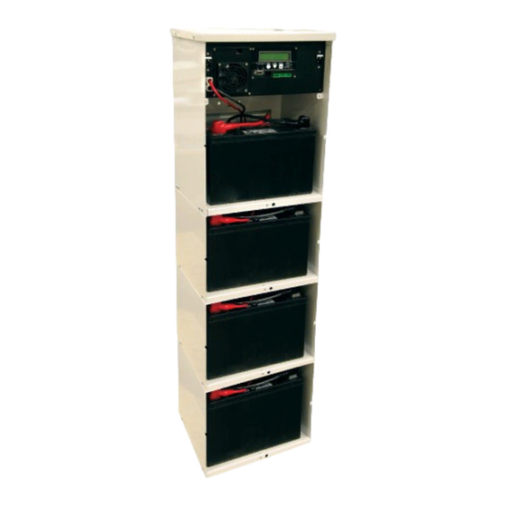
- Page 9 The Alpha Micro are designed with NEMA 3R rated enclosures for outdoor applications. Three different enclo- sures exist: (1) standard Micro, (2) Micro XL, and (3) Micro XL3. Each of these enclosures can be configured with the 300 W or the 1000 W power module (E-Module). Although the end system configuration may look different, the front panel connectors and circuit breakers along with the input and output terminal blocks are functionally the same.
- Page 10 Output terminal block Input terminal block Attachment fitting for optional battery restraining bar Wire management panel Attachment holes for mounting bracket Knockouts for wiring Front panel securing screw and attachment for user- provided lock Figure 2 — Alpha Micro Interior 017-237-B0 Rev A...
Need help?
Do you have a question about the Micro and is the answer not in the manual?
Questions and answers