Sign In
Upload
Manuals
Brands
Alpha Manuals
Power Supply
CXPS-C
User Manuals: Alpha CXPS-C Capacity Power System
Manuals and User Guides for Alpha CXPS-C Capacity Power System. We have
1
Alpha CXPS-C Capacity Power System manual available for free PDF download: Technical Manual
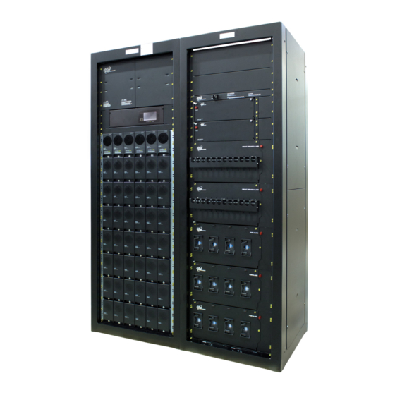
Alpha CXPS-C Technical Manual (84 pages)
Centralized Power Plant
Brand:
Alpha
| Category:
Power Supply
| Size: 14 MB
Table of Contents
Table of Contents
5
1 Safety
9
Safety Symbols
9
General Warnings and Cautions
9
Electrical Safety
10
Battery Safety
10
2 Introduction
11
Product Overview
11
Part Numbers and List Options
11
Figure 1 - CXPS-C Centralized Power Plant Basic System
11
3 Specifications
12
4 Features
15
Figure 2 - Basic Power System
15
Power Bays
16
Figure 3 - Stand-Alone Power Bay Showing DC Charge Buses
17
Figure 4 - Top View of Horizontal Inter-Bay Busbars
17
Rectifier Modules
18
Figure 5 - 4.0Kw Rectifier Front Panel Leds
18
Figure 6 - 12Kw (3-Phase) Rectifier Front Panel Leds
18
Distribution Bays
19
Figure 7 - Distribution Panel Options
20
Figure 8 - 4 Position TPL
21
Figure 9 - 12X 1 Position High Capacity Breaker
21
Figure 10 - 6X 2 Position High Capacity Breaker
22
Figure 11 - 4X 3 Position High Capacity Breaker
22
Figure 12 - 3X 4 Position High Capacity Breaker
23
Figure 13 - 2X 5 Position High Capacity Breaker
23
Figure 14 - 2X 6 Position High Capacity Breaker
24
Figure 15 - 4X2 & 4X1 Position High Capacity Breaker
24
Figure 16 - 18 Position Bullet Breaker
25
Figure 17 - 18 Position Bullet Breaker Return
25
Figure 18 - Distribution Bay-DC Distribution Bus
26
Figure 19 - Distribution Shunts
27
DC Inter-Bay Copper
28
Figure 20 - Inter-Bay DC Connections
28
Figure 21 - External Battery Return Ground Bar
29
Cordex HP Controller
30
Figure 22 - Cordex CXC HP Controller
30
Figure 23 - LCD Color Touchscreen Display
30
External Peripherals
31
Figure 24 - L-ADIO I/O Peripheral
31
Figure 25 - 6I-ADIO Peripheral
32
Figure 26 - Redundant Input Power Module
33
Figure 27 - Shelf/Bay ID
33
5 Pre-Installation Preparation
34
Site Selection
34
Tools and Test Equipment
35
Floor Loading
35
6 Inspection
36
Packing Materials
36
Check for Damage
36
General Receipt of Shipment
36
7 Frame Installation
37
Floor Drilling for Standard Anchoring
37
Figure 28 - Base Dimensions and Mounting Holes
37
Placing and Securing the Bays
38
Figure 29 - Securing Power System to Concrete Floor
38
Securing Adjacent Bays
39
Figure 30 - Bolting Adjacent Bays Together
39
Installing the Inter-Bay DC Bus Work between Adjacent Frames
40
Figure 31 - Example of Installed Inter-Bay Buswork
41
Connecting the Shunt and Inter-Bay Signal Cables
42
Figure 32 - Shunt Connections
42
Figure 33 - Inter-Bay Wiring Harness
42
Figure 34 - CAN out Port Terminator
43
Figure 35 - Controller, CAN Bus Cabling 4.0Kw Power Bay
43
Figure 36 - Controller and Shelf/Bay ID, CAN Bus and Shelf ID Cabling
44
Figure 37 - CAN Bus Termination 4.0Kw
45
Figure 38 - CAN IN/CAN out Connection 4.0Kw
45
Figure 39 - Battery Disconnect Connections
46
Mounting the Optional External Return Bar
47
Figure 40 - External Battery Return Bar Kit
47
Battery Installation
48
Figure 41 - Battery Installation
48
Figure 42 - Battery Temperature Probes
49
Battery Maintenance Report
50
8 Wiring
51
Installation Notes
51
Connecting the Frame and Reference Grounds
53
Figure 43 - Battery Return Busbars, Frame Ground and Battery Return Reference
53
AC Supply for the Rectifiers
54
Figure 44 - AC Distribution
54
Figure 45 - Pre Wired 8-Feed AC Panel - 3 Phase, 3 Wire 208/480 Vac
55
Figure 46 - Terminal Blocks for 8-Feed 3 Wire 208/480Vac Input
56
Figure 47 - Terminal Blocks for 16-Feed 208/480Vac Input
56
Figure 48 - Terminal Blocks for 6-Feed 480Vac Input
56
Distribution
57
Figure 49 - High Capacity Breaker Panel Alarm Wiring
57
Figure 50 - External Battery Return Bar Wiring
58
Figure 51 - Customer Connections Spacing
59
9 Installing Standalone Power and Distribution Bays
60
Standalone Power Bay
60
Standalone Distribution Bay
61
10 System Startup
62
Check System Connections
62
Verify AC and Power the Rectifier Shelf
62
Check Battery Polarity and Connect
62
Final Configuration and Test
62
Shelf ID Connection
63
Figure 52 - Example of a Single Bay with Two Rectifier Shelves
63
11 Test and Commissioning Overview
64
System
64
Battery
64
Documentation
64
12 Maintenance
65
Rectifiers
65
Batteries
65
Controller Lithium Battery Replacement
65
13 Warranty Statement and Service Information
66
14 Acronyms and Definitions
67
15 Certification
68
Advertisement
Advertisement
Related Products
Alpha Ecoguard CX5
Alpha Alpha CB50 Boiler
Alpha Alpha CD24R
Alpha Alpha CD24S
Alpha CFR 5000
Alpha C016-1009-10
Alpha C016-198-10
Alpha C016-1540-10
Alpha C016-1545-10
Alpha Alpha CD28C
Alpha Categories
Boiler
Power Supply
UPS
Sander
Accessories
More Alpha Manuals
Login
Sign In
OR
Sign in with Facebook
Sign in with Google
Upload manual
Upload from disk
Upload from URL