
Related Manuals for Svantek SV 277 PRO


Summary of Contents for Svantek SV 277 PRO
- Page 1 USER MANUAL SV 277 PRO MONITORING STATION Copyright © 2019 SVANTEK. Warsaw, 2019-09-02 Rev. 01.04 All rights reserved.
- Page 2 Information provided in this manual is intended to be accurate and reliable. However, Svantek assumes no responsibility for its use, or for any infringements on the rights of third parties that may result from its use.
-
Page 3: Important Notes Before Use
Then charge the battery to 100% capacity. ✓ Monitoring station and SB 272 have their own chargers, which are incompatible: SB 270 is a waterproof power supply for SV 277 PRO, whereas SB 273 is an indoor charger for SB 272. -
Page 4: Table Of Contents
Accessories included ..................7 1.3. Accessories available ..................7 2. MONITORING STATION SET ..............8 2.1. SV 277 PRO standard set and optional elements ..........8 2.1.1. SM 277 PRO - Waterproof Case ..............9 2.1.2. SD 270(A) PRO - Controller................. 12 2.1.3. - Page 5 Main communication channel ..............47 4.4.2. SMS / E-mail alarming ................. 49 4.4.3. SMS command exchange ................50 4.5. Remote Communication module of SvanPC++ ..........50 Appendix A. SV 277 PRO Technical Data ........... 51 Appendix B. List of related documents ............55...
-
Page 6: Introduction
1.1. F EATURES • SV 277 PRO is a portable monitoring station housed in an IP67 waterproof case dedicated for periodic outdoor measurements. • The station is based on the SVAN 977A instrument which can be easily removed from the case and used as a hand-held sound level meter. -
Page 7: Accessories Included
SV 277 PRO User Manual • The option for 1/3-octave real-time frequency analysis allows analysis of the noise frequency contents. The statistical analysis in 1/3 octave band is used for verification of noise sources in the environment. It can be activated at any time by entering the activation code. -
Page 8: Monitoring Station Set
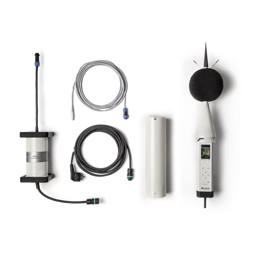
MONITORING STATION SET 2.1. SV 277 PRO STANDARD SET AND OPTIONAL ELEMENTS The SV 277 PRO station consists of two carrying cases. The main case is waterproof with an internal 17 Ah battery and internal charging unit supporting powering from an... -
Page 9: Sm 277 Pro - Waterproof Case
SV 277 PRO User Manual Additional accessories for SV 277 PRO system, not included in the standard set, but in many applications, essential for reliable system operation and task performance are: 1. Sound Calibrator (SV 36), see Chapter 2.2.1 2. external battery 33 Ah including see Chapter 2.2.2... - Page 10 SV 277 PRO User Manual The controller is fixed in the station case by a Signal Power Combo connector and can also be removed from the case. To do this the user should pull the controller up and remove it from the slot.
- Page 11 SV 277 PRO User Manual To connect a cable to a case socket, start by lining up the key on the plug and the socket, then lock the connector by turning the ring clockwise (only the ring close to the socket will rotate).
-
Page 12: Sd 270(A) Pro - Controller
USB Device 1.1 interface of the SVAN 977A (USB socket). Note: Communication of the controller or SVAN 977A with a PC requires installation of the USB drivers on your PC. USB driver for Svantek devices are available on... -
Page 13: Sp 270 - 3G Modem
SV 277 PRO User Manual Note: Before starting upgrading be sure that your SvanPC++ software is Off! If not, please Exit it before starting any upgrading. To upgrade the firmware of the controller, go through the next steps: 1. Switch off SVAN 977A and wait until all LEDs are off. -
Page 14: Svan 977A - Sound And Vibration Analyser
SVAN 977A is a Class 1 Sound & Vibration level meter as well as a real time 1/1 or 1/3 octave analyser and is a core of the SV 277 PRO system. Its role is to make measurements and save results in files, as well as to control data transfer via modem to the SvanNET server or directly to the PC. - Page 15 SV 277 PRO User Manual Note: As a part of the SV 258 PRO station SVAN 977A is powered from the external source and doesn’t use its internal batteries. Internal instrument’s batteries must be removed for correct system operation and safety reasons! Note: The station is delivered without internal batteries inside the instrument.
-
Page 16: Sa 277 - Outdoor Microphone Protection Kit
SV 277 PRO User Manual All measurement, instrument and transmission settings can be set up via SVAN 977A user interface, or remotely via the SvanNET server or SvanPC++ program. Note: See also SVAN 977A User Manual. 2.1.5. SA 277 - Outdoor Microphone Protection Kit... -
Page 17: Sb 270 - External Power Supply With Ac/Dc Converter
SV 277 PRO User Manual Note: Before installing the station at the measurement site, make sure that the protective caps on the four antibird spikes are removed. It is recommended to use the protective caps during transportation, storage and other operations with the instrument like, laboratory calibration, etc. -
Page 18: Sb 272 - External Rechargeable Battery
SV 277 PRO User Manual 2.2.2. SB 272 - External Rechargeable Battery SB 272 is an external source of DC power for the monitoring station. includes Lead-Acid rechargeable battery (33 Ah, 12 V) and is dedicated for outdoor use because of its waterproof case. The... -
Page 19: Sp 272 - Alarm Lamp
2. shift the switch to the left. 2.2.5. SP 275 - Meteo Module SP 275 is a Vaisala Weather Transmitter WXTxx type meteorological module used with the SV 277 PRO monitoring station. It measures 6 most essential weather parameters (barometric... - Page 20 SV 277 PRO User Manual Note: Do not forget to align the transmitter so that the arrow on the bottom of the transmitter points North. Note: See also Vaisala WXT530 User Guide. The controller then transfers the weather parameters to SVAN 977A, which saves them in a logger file as a history if the Meteo position is On in the Logger Results list (path: <Menu>...
-
Page 21: Operating The Station
The status of powering is indicated at the controller’s panel by a combination of DC, CHARGING, BAT 1 or BAT 2 LEDs (see Table below). Note: It is recommended that the batteries of SV 277 PRO and SB 272 are charged before going on site. - Page 22 SV 277 PRO User Manual Colour of LEDs can be red, orange or green. Colour of SVAN, 3G and EXT. I/O LEDs reflect the communication state with the corresponding unit. Colour of DC, CHARGING, BAT 1 or BAT 2 LEDs depend on the state of the power supply and charging of the internal battery.
-
Page 23: Modes Of Station Operation
Chapter 2.1.4). If one of these parameters or both are on, but the Meteo module is not connected to the SV 277 PRO the EXT. I/O LED lights red colour. After connection of the Meteo module the LED changes colour to green. If Meteo logging is off and alarms are on in the SVAN 979 instrument, then EXT I/O LED reflects the status of an external alarm lamp. -
Page 24: Configuring The Station
• in the case of SD 270A, by the LED above the TEST key. Note: USB connection between controller and PC can be established only if USB driver for SVANTEK instruments had been previously installed on the PC. USB driver can be downloaded from www.svantek.com... -
Page 25: Assembling The Station
SV 277 PRO User Manual 5. Check the Access Point Name (APN) setting in the SVAN 977A. The default setting for the APN is "internet". It’s possible that your Internet provider is using a different APN. In this case the APN must be entered manually, either via the PC software or the SVAN 977A menu (path: <Menu>... - Page 26 SV 277 PRO User Manual 5. To connect the microphone extension cable, start by lining up the key on the plug and the INPUT socket, then lock the connector by turning the ring clockwise (only the ring close to the socket will rotate).
-
Page 27: Switching On The Station
SV 277 PRO User Manual 10. The station now is ready for use. 3.6. S WITCHING ON THE STATION When the remote communication is installed, and the station is fully assembled: • Turn on the SVAN 977A instrument. The controller will turn on automatically. -
Page 28: Remote Control Via 3G Connection
SV 277 PRO User Manual REMOTE CONTROL VIA 3G CONNECTION The SV 277 PRO station is designed to work with a 3G modem. Planning and deploying the remote-control system of the SV 277 PRO station doesn’t require any extensive knowledge in the field of telecommunication. Once all steps described –... - Page 29 Once logged in you can use the web interface to manage the monitoring station. Note: Ask your local SVANTEK distributer to create the SvanNET account for you and assign your new station to your SvanNET account.
-
Page 30: Station List View
SV 277 PRO User Manual The SvanNET interface depends on the package of tools assigned to your account and access level and includes: – projects tools (Project list) – individual stations tools (Station list). If you have extended SvanNET package, you can use both tools. If you have standard SvanNET package, only Station list tool is available. -
Page 31: Status View
SV 277 PRO User Manual Information about the communication with the station: green - correct, in progress; yellow - the station doesn’t respond to the command for a long time; red – the station is not connected to SvanNET. Battery status. When you click this icon, information about charging level will be displayed. - Page 32 SV 277 PRO User Manual Click +ADD ALARM in the pop-up box and a new Alarm(1) with CONDITIONS, ACTIONS and MEASUREMENT POINTS areas will appear. Alarms are based on Conditions and relate to Actions, that are default e-mails to the specified recipients, and refer to Measurement points.
-
Page 33: Log Views
SV 277 PRO User Manual 3. click the E-mail button to edit e-mail recipients. 4. click the Assign button to refer alarm to the station(s). 5. Made selections are displayed in the ACTIONS and MEASUREMENT POINTS areas. 4.2.2. LOG views There are three station logs, that register system events, connections and data transfer: 1. -
Page 34: Web Interface View
SV 277 PRO User Manual 2. Data Connection log which registers history of station connections. In the upper line you can: refresh the log, select the required period of records to be displayed and rewind records. 3. Data transfer log which registers history of data transfers (uploads). -
Page 35: Live Data View
SV 277 PRO User Manual The VIEW button switches you to the Live data view (see Chapter 4.3.1) in which you can view broadband results, 1/1 or 1/3 octave spectra and a time-history. The STATUS button switches you to the station status view (see Chapter 4.3.3) in which you can check the... - Page 36 SV 277 PRO User Manual Instantaneous and Summary results are updated every second. The type of the measured result along with filter and detector as well as profile in which this result is measured is presented in the selector field below the result value. To change the displayed result, click the selector button and choose the profile and the result.
- Page 37 SV 277 PRO User Manual There are four results (Leq, Lpeak, Lmax and Lmin) measured with appropriate weighting filters and detector types and available for each measurement profile from the pop-down list. The SPECTRUM RESULTS tab displays current 1/1 or 1/3 octave Instant and Averaged results (LZeq) and three Total results.
-
Page 38: Configuration Views
SV 277 PRO User Manual Note: Spectra can only be displayed, when Octave 1/1 or Octave 1/3 → measurement function been selected Configuration Measurement setup tab. 4.3.2. Configuration views The Configuration view consists of several tabs that enable configuring measurement parameters (MEASUREMENT SETUP), saving measurement results (STORAGE) and triggering alarms based on events (EVENT TRIGGER). - Page 39 SV 277 PRO User Manual Note: Definitions and formulae for measurement results are presented in Appendix D of the SVAN 977A User Manual. In the STORAGE tab, you can: 1. Enable data logging 2. Program splitting of the logger file (Logger splitting) 3.
- Page 40 SV 277 PRO User Manual The Logger splitting position enables splitting of logger files and selecting the splitting mode: Disabled, Every 15 m, Every 30 m, Every 1 h and Every day. If Every day is selected, you can define up to six points during a day when splitting will take place.
- Page 41 SV 277 PRO User Manual Note: To ensure saving of any results you should enable data logging. Summary results are saved in the same file with Time history results. Note: All files with measurement result are automatically named in accordance with the rule: some prefix (string of letters) and number (string of digits) increased by one for newly created files.
- Page 42 SV 277 PRO User Manual Creating Events To create new event, click the field. The new Event area will appear in which you can: 1. rename the event, switch it on/off or delete it, clicking on the appropriate field in the area, 2.
- Page 43 SV 277 PRO User Manual If you click the TRIGGER button, the TRIGGER CONDITIONS configuration box will pop-up. In this box, you can add the condition type: Threshold. The Threshold condition can be Level+ Level- type (Mode). The condition is fulfilled...
- Page 44 SV 277 PRO User Manual After confirmation (OK) the pop-up box closes, and the selection will be presented in the line of the TRIGGER button. Creating Actions To create new action, click the field and in the ADD EVENT ACTION pop-up box,...
- Page 45 SV 277 PRO User Manual The SMS Alarm action sends the SMS note (Message) to the defined recipient’s phones, which selected from ADDRESS BOOK after clicking field. Min. break defines the minimum time break between two consequent SMSs. The E-mail Alarm action sends the E-mail note (Subject and Message) to the defined recipient’s addresses, which are selected...
-
Page 46: Status View
SV 277 PRO User Manual 4.3.3. STATUS view The STATUS view is similar to that described in the Chapter 4.2.1. The difference is that instead of STATUS ALARMS, in this view, you can start/stop measurements. 4.3.4. STORAGE view The file storage window presents a list of files saved in the instrument’s SD-card memory. -
Page 47: Interface Functionalities Of 3G Modem
Manual. SvanPC++ assures this connection and provides data download, performance validation and measurement start/stop. Main communication channel of SV 277 PRO can be established by one of two available methods: TCP Client or TCP Server. The SV 277 PRO stations support SSL (Secure Socket... - Page 48 Note: TCP Client mode is used in the SvanNET service. SV 277 PRO uses the TCP Client mode to connect to SvanNET (this is the default setting of SVAN 977A). The user also connects to SvanNET via web browser or SvanPC ++, and the service creates a "bridge"...
-
Page 49: 4.4.2. Sms / E-Mail Alarming
SMS/E-mail alarming functionality allows SV 277 PRO to inform the user about exceeded thresholds by SMS and/or E-mail notification. SV 277 PRO can send an SMS to a defined number(s) and/or an E-mail to a defined address(s) with alarm, including the current value of the monitored result against the threshold level. -
Page 50: Sms Command Exchange
SV 277 PRO User Manual 4.4.3. SMS command exchange SMS command exchange allows any command from the Appendix A. Remote Control to SVAN 977A User Manual to be exchanged via SMS. By sending a command as specified by the said document, SV277 PRO can provide a response. This feature is particularly useful when retrieving the current state of the station. -
Page 51: Appendix A. Sv 277 Pro Technical Data
SV 277 PRO User Manual APPENDIX A. SV 277 PRO TECHNICAL DATA Parameter Value/ Description Physical data SM 277 PRO – 300 x 260 x 190 mm Dimensions SA 250 – 450 x 400 x 155 mm SM 277 PRO – ~10 kg Weight SA 250 –... - Page 52 SV 277 PRO User Manual Parameter Value/ Description up to 30W ±5% 13 SV 277 PRO power consumption including charging 14 External DC input voltage: 10,5 V to 28 V Note: When external DC input voltage is in the range 11 V to 15...
- Page 53 SV 277 PRO User Manual Parameter Value/ Description Note: With the use of Outdoor Airport type compensation filter (filter must be defined in SVAN 977A, see Chapter 2.1.4) the acoustic characteristics of SA 277 conforms the class 1 sound meters and IEC 61672:2002 standard for the direction 0 degree (normal direction regarding the microphone membrane).
- Page 54 SV 277 PRO User Manual Parameter Value/ Description 30 3G modem HSDPA Cat.8 / HSUPA Cat.6 data rates specifications DL: max. 7.2 Mbps, UL: max. 5.76 Mbps EDGE Class 12 data rates DL: max. 237 kbps, UL: max. 237 kbps GPRS Class 12 data rates DL: max.
-
Page 55: Appendix B. List Of Related Documents
SV 277 PRO User Manual APPENDIX B. LIST OF RELATED DOCUMENTS 1. SVAN 977A User Manual (www.svantek.com) 2. SvanNET User Manual (www.svantek.com) 3. SvanPC++ User Manual (www.svantek.com) 4. SA 277 Assembly Guide (www.svantek.com) 5. GeMalto® EHS6 Terminal User Manual (www.gemalto.com)
Need help?
Do you have a question about the SV 277 PRO and is the answer not in the manual?
Questions and answers