Haworth Upside Assembly Instructions Manual
Hide thumbs
Also See for Upside:
- Assembly instructions manual (20 pages) ,
- Installation instructions manual (15 pages)
Advertisement
Quick Links
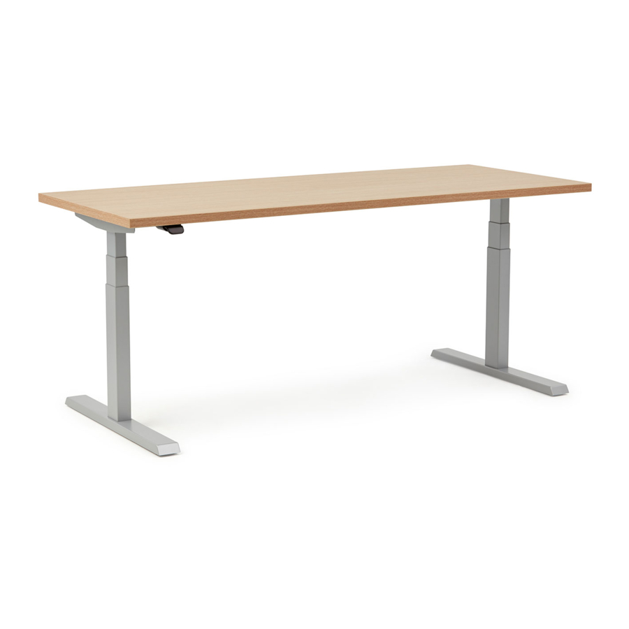
Upside
Assembly Instructions
Congratulations on
your purchase of a
new Upside table!
For assembly assistance, visit Haworth.com, or call: 1-800-426-8562, or email support@haworth.com
Ready to put some movement into your day?
We know you want to get up and running as soon as possible, but
before you dive right into setting up your table, be sure to:
1. Grab a friend to help you with the lifting. They can also help you
hold parts in place during assembly to make things a little easier.
2. Make sure you have all your parts and hardware, and gather the
necessary tools and safety equipment.
3. Follow all the steps and synchronize your table before using it.
That's it! Once you've got your table assembled and synchronized,
you'll be ready to enjoy the freedom to change position as you work
anytime you want.
Height-Adjustable Table
Advertisement

Related Manuals for Haworth Upside


Summary of Contents for Haworth Upside
- Page 1 That's it! Once you've got your table assembled and synchronized, you'll be ready to enjoy the freedom to change position as you work new Upside table! anytime you want. For assembly assistance, visit Haworth.com, or call: 1-800-426-8562, or email support@haworth.com...
-
Page 2: Important Safety Instructions
9. Connect this furnishing to a properly grounded outlet only. See grounding instructions. Electrical Rating Figure 1 120V, 60Hz, 6.25A for Upside Standard 2 leg tables Grounded 120V, 60Hz, 6A for Upside Value 2 leg tables Outlet Grounded... -
Page 3: Assembly Overview
Upside™ Height-Adjustable Table Assembly Instructions Tools Required Optional: For caster installation only. 1/8” 13mm Drill Bit Tape Level Assembly Overview S200 S200 S201 S201 Scale 1 : 1 S206 (S-90) M6 X 8mm Set Screw (S209) M6 X 14mm Button Head... - Page 4 (A) Worksurface (B) End Brackets (C) Paddle Handset (D) Leg Column (E) Foot (F) Control Box (G) Power Cord (H) Frame and (H1) Rails (J) Motor Extension (K) Cable Clips Cable 10 Qty. (S200) (S209) (S201) (S202) (S-90) 3mm Allen Wrench M6*10 Machine Screws M6*14 Machine Screws ST5*20 Wood Screws...
- Page 5 Pull frame (H) off rails (H1) as shown Customer Service 800 426 8562 E.C.O. No 478-026 Part No 6100-0167 Rev 1 Page 5 of 20...
- Page 6 Attach column (D) to frame (H) - Slightly lift column to align holes LOOSE TIGHT Important Install screws (S200) 4 Qty. LOOSELY (S200) M6 X 10mm Button Head M6*10 Machine Screws qty 12pcs S200 4mm Allen Wrench S200 Repeat 2nd step 2 to attach 2nd column (D) to frame (H) Important LOOSE TIGHT...
- Page 7 Attach bracket (B) to column (D) - Tilt column (D) and frame (H) slightly to align holes LOOSE TIGHT Important Install screws (S200) LOOSELY 2 Qty. (S200) M6 X 10mm Button Head M6*10 Machine Screws qty 12pcs 4mm Allen S200 Wrench Repeat step 4 to attach 2nd bracket (B) to column (D) LOOSE...
- Page 8 Tighten all 6 screws (S200) TIGHTEN 6 Qty. TIGHTEN S200 (S200) M6 X 10mm Button Head Important TIGHTEN all 6 screws (S200) 4mm Allen Wrench TIGHTEN S200 TIGHTEN TIGHTEN Repeat for other side and tighten all 6 screws (S200) 6 Qty. TIGHTEN (S200) M6 X 10mm Button Head TIGHTEN...
- Page 9 Slide rails (H1) and frame (H) together LONG TAB Important Install rails (H1) as shown with slots facing each other and long tab on the bottom Customer Service 800 426 8562 E.C.O. No 478-026 Part No 6100-0167 Rev 1 Page 9 of 20...
- Page 10 Repeat step 8 for other side and slide frame (H) onto rails (H1) Customer Service 800 426 8562 E.C.O. No 478-026 Part No 6100-0167 Rev 1 Page 10 of 20...
- Page 11 Attach frame (H) to worksurface (A) - Align holes in brackets (B) with holes in worksurface (A) 6 Qty. (S201) M5 X 20mm Truss Head Screw ST5*20 Wood Screws qty 10pcs S201 NOTE: Holes towards the front. NOTE: Front of worksurface has thicker edge band with a rounded edge.
- Page 12 Drilling may be required to start screws (S201) NOTE: You may need to drill 1/4” deep holes to start the screws. 4 Qty. 1/4” Deep (S201) M5 X 20mm Truss Head Screw 1/8” Drill Bit Tape ST5*20 Wood Screws qty 10pcs Install 4 screws (S201) as shown S201 4 Qty.
- Page 13 Install 8 set screws (S-90) as shown S-90 3mm Allen 8 Qty. Wrench (S-90) M6 X 8mm Set Screw M6*8 Set Screws qty 8pcs S-90 3mm Allen Wrench Important Make sure setscrew (S-90) NOTE: Center rails (H1) engage rails (H1). before tightening set screws (S-90).
- Page 14 CASTER INSTALLATION - OPTIONAL Insert casters (D2) and tighten with wrench as shown Remove foot pads (D1) as shown NOTE: Casters are optional and ordered separately. NON-LOCKING CASTER 13mm Wrench LOCKING CASTER Customer Service 800 426 8562 E.C.O. No 478-026 Part No 6100-0167 Rev 1 Page 14 of 20...
- Page 15 Plug cable (D) into control box (F) as shown Install control box (F) as shown S202 2 Qty. (S202) M5 X 16mm Truss Head Screw S202 ST5*16 Wood Screws qty 2pcs Important Make sure control box (F) NOTE: For frame (H) less than 46 inches wide is firmly attached to the mount control module (F) outside of frame (H) worksurface...
- Page 16 Plug motor extension cable (J) into control box (F) and column (D) as shown Plug power cable (G) into control box (F) as shown Customer Service 800 426 8562 E.C.O. No 478-026 Part No 6100-0167 Rev 1 Page 16 of 20...
- Page 17 Install paddle handset (C) with hand screwdriver ONLY Screwdriver NOTE: Paddle screw (S206) must be installed straight and fully seated. Crooked or partial installation of screws (S206) may interfere with 2 Qty. the paddle (C) performance (both standard and (S206) M4 X 30mm Pan Head Screw S206 programmable).
- Page 18 With a helper, flip table onto its feet DO NOT USE TABLE UNTIL ALL STEPS AND SYNCHRONIZATION HAVE BEEN COMPLETED STOP! FLIP TABLE ONTO FEET Level table as shown STOP! DO NOT USE TABLE UNTIL ALL STEPS AND STOP! SYNCHRONIZATION HAVE BEEN COMPLETED Customer Service 800 426 8562 E.C.O.
- Page 19 SYNCHRONIZE TABLE Lower table all the way down using paddle handset (C) Lower table all the way down and Important release paddle Prior to first use, synchronize the motors in the columns (D) - If table is already at lowest position skip to step 26. - If table will not go up or down, skip to step 26 then in step 27;...
- Page 20 SYNCHRONIZATION INTERVALS Be sure to synchronize your table as noted below to keep it calibrated and functioning properly. 1) Before first use 2) After any cables/cords are disconnected/reconnected or after servicing any component (swapping out paddles, disconnecting/reconnecting the cables/cords, etc.) 3) After any interruption in power or loss of power (or any time the power cord is unplugged from the outlet and plugged back in) 4) Monthly to maintain optimum table performance...
Need help?
Do you have a question about the Upside and is the answer not in the manual?
Questions and answers