Table of Contents
Advertisement
Quick Links
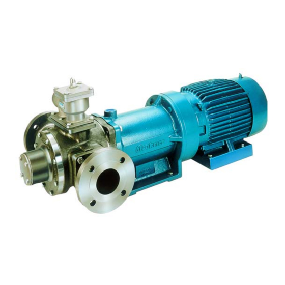
BLACKMER SEAL-LESS PUMPS
INSTALLATION OPERATION AND MAINTENANCE INSTRUCTIONS
MODELS: SMVP50C, SMVP100C, SMVP200C, SMVP300C
TABLE OF CONTENTS
Technical Data ...................................................... 2
Initial Pump Start Up Information .......................... 2
Pre-Installation Cleaning ...................................... 3
Location and Piping .............................................. 3
Check Valves ........................................................ 3
Pump Mounting .................................................... 3
Motor Installation .................................................. 4
Pre-Start Up Check List ........................................ 5
Start Up Procedures ............................................. 5
Pump Rotation ...................................................... 5
Reverse Rotation .................................................. 5
Flushing the Pump ................................................ 5
Pump Relief Valve ................................................ 6
Relief Valve Setting and Adjustment .................... 6
Strainers ............................................................... 7
Lubrication ............................................................ 7
Vane Replacement ............................................... 8
Pump Disassembly ............................................... 8
Pump Assembly .................................................... 9
TROUBLE SHOOTING .....................................
NOTE: Numbers in parentheses following individual parts
indicate reference numbers on Blackmer Parts Lists 108-
B02 and 108-B03.
NOTE: Blackmer pump manuals & parts lists may be
obtained from Blackmer's website (www. blackmer. com)
or by contacting Blackmer Customer Service
This is a SAFETY ALERT SYMBOL.
When you see this symbol on the product, or in the
manual, look for one of the following signal words and be
alert to the potential for personal injury, death or major
Warns of hazards that WILL cause serious personal injury,
death or major property damage.
Page
Warns of hazards that CAN cause serious personal injury,
death or major property damage.
Warns of hazards that CAN cause personal injury
Indicates special instructions which are very
important and must be followed.
Blackmer Seal-Less pumps MUST only be installed In
systems, which have been designed by qualified
engineering personnel. The system MUST conform to
all applicable local and national regulations and safety
standards.
This manual is intended to assist in the installation and
operation of the Blackmer Seal-Less pumps, and
MUST be kept with the pump.
Blackmer Seal-Less pump service shall be performed
11
by qualified technicians ONLY. Service shall conform
to all applicable local and national regulations and
safety standards.
Thoroughly review this manual, all instructions and
hazard warnings, BEFORE performing any work on the
Blackmer Seal-Less pumps.
Maintain ALL system and Blackmer Seal-Less pump
operation and hazard warning decals.
960902
INSTRUCTIONS NO. 108-B00
Section
108
Effective
March 2018
Replaces
July 2015
SAFETY DATA
property damage
or property damage.
NOTICE:
NOTICE:
Advertisement
Table of Contents

Subscribe to Our Youtube Channel
Related Manuals for BLACKMER SMVP50C


Summary of Contents for BLACKMER SMVP50C
-
Page 1: Table Of Contents
B02 and 108-B03. Thoroughly review this manual, all instructions and hazard warnings, BEFORE performing any work on the NOTE: Blackmer pump manuals & parts lists may be Blackmer Seal-Less pumps. obtained from Blackmer’s website (www. blackmer. com) or by contacting Blackmer Customer Service Maintain ALL system and Blackmer Seal-Less pump operation and hazard warning decals. -
Page 2: Pump Data
+ Differential Pressure Technical Data is for standard materials of construction. Consult Blackmer Material Specs for optional materials of construction. * Conversion is based on a specific gravity of 1.0. Failure to use care when handling magnets can cause personal injury... -
Page 3: Installation
When using a foot mounted 284-286TC motor frame for start up. SMVP200C models or a foot mounted 254-256TC motor frame for SMVP50C/100C models, shims are required under the ALL piping and fittings MUST be properly supported to magnet housing to support the motor frame. -
Page 4: Motor Installation
Slide the motor adapter ring (86) over the outer magnet to the “C-Face” of the motor. Ensure that the flange of On SMVP50C/100C models: torque to 9 ft lbs. (12.2 Nm) the motor adapter ring is fully and squarely seated. -
Page 5: Operation
OPERATION If equipped, check the pressure relief setting of the pump relief valve by gradually closing a valve in the discharge line momentarily and noting the reading on the pressure Operation without coupling guard can gauge. This pressure reading should be 10-20 psi (.69 – cause serious personal injury, death or 1.4 bar) higher than the maximum system operating major property damage... -
Page 6: Pump Relief Valve
(2) outward, or COUNTERCLOCKWISE. Install a new R/V O-ring / gasket (88), and re-attach the R/V cap. Refer to corresponding Blackmer pump parts lists for relief valve spring pressure ranges. Unless specified otherwise, pumps are supplied from the factory with the relief valve adjusted to the mid-point of the spring range. -
Page 7: Maintenance
MAINTENANCE Failure to disconnect and lockout Operation without guards in place can electrical power before attempting cause serious personal injury, major maintenance can cause shock, burns or property damage, or death. death Hazardous voltage. Do not operate Can shock, burn or without guard cause death. -
Page 8: Vane Replacement
14. RELIEF VALVE DISASSEMBLY (if equipped) 4. On SMVP50C/100C models: While facing the outboard end of the pump, grasp the pump cylinder (12) with two a. Remove the valve cap (1) turn the adjusting screw (2) hands and firmly pull the pump assembly from the magnet to relieve the spring pressure. -
Page 9: Pump Assembly
MAINTENANCE MAGNET HOUSING DISASSEMBLY 1. Remove the four housing/adapter capscrews (54B), and pull the motor, motor adapter (86) and outer magnet (53) from the magnet housing (57). 2. Remove the motor adapter capscrews (56), and the motor adapter (86) from the motor. 3. - Page 10 Insert new vanes into the rotor slots with the rounded damaged, bearings MUST be replaced. edges outward, and the vane relief grooves facing On SMVP50C/100C models: if the inside diameter of the TOWARDS the direction of rotation. Refer back to bearing measures 1.196" (30.38mm) or greater at any Figure 3.
-
Page 11: Troubleshooting
MAINTENANCE OUTER MAGNET ASSEMBLY 6. Using an appropriately sized hoist CAREFULLY slide the Follow instructions given in the MOTOR INSTALLATION pump assembly into the mounted magnet housing. Section of this Manual. On SMVP200C/300C models if motor, adapter ring, and outer magnet are in place, the jackscrews (54C), installed FINAL ASSEMBLY in the magnet housing during disassembly, will hold the When Outer Magnet &... - Page 12 1809 Century Avenue, Grand Rapids, Michigan 49503-1530, U.S.A. Telephone: (616) 241-1611 / Fax: (616) 241-3752 Email: blackmer@blackmer.com / Internet: www. blackmer .com...
Need help?
Do you have a question about the SMVP50C and is the answer not in the manual?
Questions and answers