Table of Contents
Advertisement
Quick Links
Advertisement
Table of Contents

Subscribe to Our Youtube Channel
Related Manuals for Digi ConnectCore 8X SBC Pro


Summary of Contents for Digi ConnectCore 8X SBC Pro
- Page 1 ConnectCore 8X SBC Pro Hardware Reference Manual...
- Page 2 Information in this document is subject to change without notice and does not represent a commitment on the part of Digi International. Digi provides this document “as is,” without warranty of any kind, expressed or implied, including, but not limited to, the implied warranties of fitness or merchantability for a particular purpose.
- Page 3 Trace (if possible) Description of issue Steps to reproduce Contact Digi technical support: Digi offers multiple technical support plans and service packages. Contact us at +1 952.912.3444 or visit us at www.digi.com/support. Feedback To provide feedback on this document, email your comments to techcomm@digi.com...
-
Page 4: Table Of Contents
Contents About the ConnectCore 8X SBC Pro Overview Features and functionality Block diagram Connectors, jumpers, and switches Top view Bottom view Description Interfaces Power interfaces DC-in jack connector Additional power connector Coin cell connector 5V supply connector 3.3V supply connector... - Page 5 Specifications Electrical specification Supply voltages Power consumption Mechanical specification Environmental specification WLAN specification Regulatory information and certifications United States FCC Labeling requirements Maximum power and frequency specifications (FCC) FCC notices FCC-approved antennas RF exposure Operating frequency Europe CE mark OEM labeling requirements CE labeling requirements Declarations of Conformity Approved antennas...
-
Page 6: About The Connectcore 8X Sbc Pro
About the ConnectCore 8X SBC Pro Overview The ConnectCore 8X SBC Pro is an ultra compact Pico-ITX board featuring the Digi ConnectCore 8X system-on-module that integrates an NXP i.MX 8X application processor, LPDDR4 memory, eMMC flash memory, WLAN/Bluetooth, power management IC for optimized power consumption applications and a microcontroller assistant (MCA) for supporting additional functionality. - Page 7 BOTTOM side: 6.8 mm (PCIe connector) (Host PCBs must have a cutout to accommodate the components on the bottom side of the module.) Note Some of the functionality mentioned above is specific to a ConnectCore 8X SBC Pro variant. ConnectCore® 8X SBC Pro Hardware Reference Manual...
-
Page 8: Block Diagram
About the ConnectCore 8X SBC Pro Block diagram Block diagram ConnectCore® 8X SBC Pro Hardware Reference Manual... -
Page 9: Connectors, Jumpers, And Switches
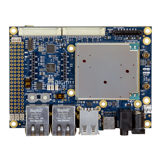
About the ConnectCore 8X SBC Pro Connectors, jumpers, and switches Connectors, jumpers, and switches Top view ConnectCore® 8X SBC Pro Hardware Reference Manual... -
Page 10: Bottom View
About the ConnectCore 8X SBC Pro Connectors, jumpers, and switches Bottom view Description Connector Interface Manufacturer Manufacturer part number 3.3V output Molex 53047-0210 5V output Molex 53047-0210 5V power-in jack Bobbintron CSCD443CCS011B00G 5V power in TE Connectivity 640456-2 Coin cell... - Page 11 About the ConnectCore 8X SBC Pro Connectors, jumpers, and switches Connector Interface Manufacturer Manufacturer part number Console Molex 53047-0410 Ethernet 1 XMultiple XMG-J1B2211NPA-1-DIG Ethernet 2 XMultiple XMG-J1B2211NPA-1-DIG LVDS 0 Hirose DF14A-20P-1.25H MIPI camera SFW15S-2STE1LF LVDS 1 Hirose DF14A-20P-1.25H Parallel camera...
-
Page 12: Interfaces
Interfaces Power interfaces Boot mode Debug interfaces Communication interfaces Multimedia interfaces Storage interfaces Expansion and user interfaces ConnectCore® 8X SBC Pro Hardware Reference Manual... -
Page 13: Power Interfaces
Power interfaces DC-in jack connector A 5V DC-in power jack connector (J4) provides power to the entire ConnectCore 8X SBC Pro system. An overvoltage circuit protects the SBC from voltages higher than 6.5V (up to 12V). Behind the overvoltage protection, a 5V load switch (U2) controls the power delivered to the SBC. The enable pin of the power switch is controlled through 5V_SBC_PWR_ON signal from the CPU (GPIO0_13). -
Page 14: Supply Connector
Together with the 5V supply connector, another 2-pin, 1.25 mm pitch straight connector is supported on the ConnectCore 8X SBC Pro providing a regulated 3.3V supply for powering external circuitry. The 3.3V power supply is generated on a buck regulator of the ConnectCore 8X PMIC (3V3_EXT power rail), which is also used on-board for powering many interfaces of the ConnectCore 8X SBC Pro carrier board. -
Page 15: Debug Interfaces
Debug interfaces JTAG The ConnectCore 8X SBC Pro provides a Tag Connect footprint for accessing the i.MX 8X JTAG debug port. This footprint is located on the bottom side of the board. The ConnectCore 8X SBC Pro provides two options for programming and debugging the Microcontroller Assist carried by the ConnectCore 8X SOM: The first option is a 2x5, 1.27 mm pitch pin header (J9) on the top side of the board that, by default, is... -
Page 16: Communication Interfaces
For power management purposes, a dedicated power switch allows you to control the power over the Ethernet PHYs. USB Host The ConnectCore 8X SBC Pro offers support for four USB Host interfaces through a USB Hub controller: ConnectCore® 8X SBC Pro Hardware Reference Manual... -
Page 17: Usb 3.0
3A. Note While the USB 3.0 bus was not supported in ConnectCore 8X SBC Pro first-availability kits, USB 3.0 is supported on the USB C-type connector starting with version 3 of the ConnectCore 8X SBC Pro (Digi part number 30015752-03 or 50001990-01 from revision 1P on (1P, 2P, A, B, ...). - Page 18 For power management purposes, a dedicated 3.3V regulator allows you to control the power over the PCIe interface. The ConnectCore 8X SBC Pro has two 2.6 mm metalized drills supporting full-size PCI Express cards. The following table shows the pinout of the PCIe connector:...
-
Page 19: Xbee
3.3V power supply line. XBee The ConnectCore 8X SBC Pro provides an XBee socket supporting the connection of Digi XBee/XBee- PRO modules. The XBee socket consist of two 10-pin, 2 mm pitch connectors (J22 and J23) which follow the standard pinout of the XBee modules:... - Page 20 In fact, some current travels through the I/Os to the module even after the regulator is disabled. If your design requires fully disconnecting the XBee socket from the ConnectCore 8X module, Digi recommends you use bus switches for all I/Os connected to the XBee socket.
-
Page 21: Multimedia Interfaces
Interfaces Multimedia interfaces Note The USB bus connected to the XBee socket is also connected to the expansion header. See Host for detailed information. Multimedia interfaces LVDS/MIPI-DSI display The two MIPI-DSI/LVDS combo PHYs supported by the ConnectCore 8X module are available over two different display connectors (J14 and J16) on the top side of the board: MIPI_DSI0 bus is connected to J14. -
Page 22: Mipi Camera
5V power supply line. MIPI camera The ConnectCore 8X SBC Pro provides one MIPI camera interface compliant with the MIPI CSI-2 specification. A MIPI D-PHY is supported by the i.MX8X CPU, allowing direct connections between the module and a MIPI CSI-2 compliant camera sensor. -
Page 23: Parallel Camera
Interfaces Multimedia interfaces Parallel camera The ConnectCore 8X SBC Pro provides one parallel camera interface (CSI). It is composed of an 8-bit data bus, a master clock from the i.MX8X CPU and three synchronization signals (PIXCLK, HSYNC and VSYNC). This interface is available over a 20-pin, 0.5 mm pitch FCC connector (J17) located in top side of the... -
Page 24: Storage Interfaces
Interfaces Storage interfaces Storage interfaces MicroSD A microSD socket (J10) is located on the bottom side of the board. This interface is connected to the USDHC1 controller of the i.MX 8X CPU. Expansion and user interfaces Expansion connector Two 2-row, 40-pin, 2.54 mm pitch headers (J20 and J27) are supported by the ConnectCore 8X SBC Pro board. - Page 25 Interfaces Expansion and user interfaces Description Signal name Signal name Description Connected to on-module PCM_IN PCM_CLK Connected to on-module wireless MAC. wireless MAC. Connected to on-module PCM_SYNC PCM_OUT Connected to on-module wireless MAC. wireless MAC. Connected to on-module LTE_PRI GPS_COEX Connected to on-module wireless MAC.
-
Page 26: User Leds
Using these lines for another purpose could alter functionality of the ConnectCore 8X SBC. User LEDs Two user LEDs are located on the top side of the ConnectCore 8X SBC Pro board. Both LEDs are connected to GPIOs from the MCA as follows:... -
Page 27: Specifications
Specifications Expansion and user interfaces Specifications Electrical specification Power consumption Mechanical specification Environmental specification WLAN specification ConnectCore® 8X SBC Pro Hardware Reference Manual... -
Page 28: Electrical Specification
ConnectCore 8X. Mechanical specification The ConnectCore 8X SBC Pro is a 100mm x 72mm pico-ITX board. Four 3.2mm drills are located on the four corners of the PCB for assembling the board into an enclosure. These drills have a 5.5mm round metalized area for the screws and nuts. - Page 29 Regulatory information and certifications Note The ConnectCore 8X SBCPro complies with Part 15 of the United States FCC rules and regulations. United States FCC Europe Canada (IC) Japan ConnectCore® 8X SBC Pro Hardware Reference Manual...
-
Page 30: United States Fcc
Regulatory information and certifications United States FCC United States FCC The ConnectCore 8X SBCPro complies with Part 15 of the FCC rules and regulations. Compliance with the labeling requirements, FCC notices and antenna usage guidelines is required. To fulfill FCC Certification, the OEM must comply with the following regulations: The system integrator must ensure that the text on top side of the module is placed on the outside of the final product. -
Page 31: Fcc Notices
Regulatory information and certifications United States FCC Peak antenna Channel band gain Technology bandwidth Channel number (Center frequency, MHz) 5 GHz 4.6 dBi WLAN 36(5180), 40(5200), 44(5220), 48(5240), 52 (5260), 56(5280), 60(5300), 64 (5320), 100 (5500), 104(5520), 108(5540), 112(5560), 116 (5580), 120(5600), 124(5620), 128(5640), 132 (5660), 136(5680), 140(5700), 149 (5745), 153 (5765), 157(5785), 161(5805), 165(5825) - Page 32 Regulatory information and certifications United States FCC Antenna used to certify the ConnectCore 8X wireless SBCPro Antenna Peak antenna Directional type Supplier Antenna part no. Freq. (MHz) gain (dBi) gain (dBi) YAGEO ANTX100P001B24553 2402~2480 7.61 5150~5250 7.91 5250~5350 6.91 5470~5725 8.11 5725~5850 8.11...
-
Page 33: Rf Exposure
Regulatory information and certifications United States FCC Antenna Peak antenna Directional type Supplier Antenna part no. Freq. (MHz) gain (dBi) gain (dBi) Ethertronic 1001932 2402~2480 5.51 5150~5250 8.01 5250~5350 8.01 5470~5725 8.01 5725~5850 8.01 TAOGLAS FXP831.07.0100C 2402~2480 6.01 5150~5250 8.51 5250~5350 8.51 5470~5725... -
Page 34: Europe
The CE marking must be affixed visibly, legibly, and indelibly. Declarations of Conformity Digi has issued Declarations of Conformity for the ConnectCore 8X SBCPro concerning emissions, EMC, and safety. For more information, see http://www.digi.com/resources/certifications. ConnectCore® 8X SBC Pro Hardware Reference Manual... -
Page 35: Approved Antennas
Regulatory information and certifications Europe Important note Digi customers assume full responsibility for learning and meeting the required guidelines for each country in their distribution market. Refer to the radio regulatory agency in the desired countries of operation for more information. -
Page 36: Canada (Ic)
Regulatory information and certifications Canada (IC) Transmitter Frequency (MHz) Maximum Output Power Radio Type / Description WLAN 5G 802.11a 5150 ~ 5350 22.16 dBm 5470 ~ 5725 21.99 dBm 5725 ~ 5850 13.17 dBm 802.11n_20M 802.11ac_20M 5150 ~ 5350 22.22 dBm 5470 ~ 5725 22.00 dBm 5725 ~ 5850... -
Page 37: Transmitters With Detachable Antennas
Regulatory information and certifications Canada (IC) Required End Product Labeling Any device incorporating this module must include an external, visible, permanent marking or label which states: “Contains IC : 1846A-CCIMX8” Obligation d'étiquetage du produit final: Tout dispositif intégrant ce module doit comporter un externe, visible, marquage permanent ou une étiquette qui dit: "Contient IC : 1846A-CCIMX8”... -
Page 38: Approved Antennas
Regulatory information and certifications Japan Approved antennas The same antennas have been approved for Canada as stated in the FCC table for use with the ConnectCore 8X module. Japan 電 波 法 により 5GHz帯 は屋 内 使 用 に限 り ます。 This device has been granted a designation number by Ministry of Internal Affairs and Communications according to: Ordinance concerning Technical Regulations Conformity Certification etc. - Page 39 Regulatory information and certifications Japan Label text Note Due to space constraints, the ConnectCore 8X module label doesn’t support radio marking for Japan. If space allows, end product label should support radio marking for Japan. If not, radio marking shall be documented in the user manual. Note The warning “Indoor only(5GHz)”...
Need help?
Do you have a question about the ConnectCore 8X SBC Pro and is the answer not in the manual?
Questions and answers