
Related Manuals for Eneo IAM-6MC1001MTA

Summary of Contents for Eneo IAM-6MC1001MTA
- Page 1 User Manual Ethernet Coax Transmitter/Receiver, Data & Power over Coax, 1 x RJ-45, 1 x BNC IAM-6MC1001MTA IAM-6MC1001MRA...
- Page 2 Safety instructions • Before switching on and operating the system, first read this safety advice and the operating instructions. • Keep the operating instructions in a safe place for later use. • Installation, commissioning and maintenance of the system may only be carried out by authorised individuals and in accordance with the installation instructions - ensuring that all applicable standards and guidelines are followed.
-
Page 3: Table Of Contents
Contents 1. Quick Installation Guide ..................3 1.1. Package Contents ..........................3 1.2. Overview ............................3 1.3. Features............................3 1.4. Hardware Overview ..........................4 1.5. Product Installation Guide.......................5 1.6. Product Application .........................5 1.7. Network Password Change .......................6 1.8. LED Indicators .............................7 1.9. Specification ............................7 1.10. -
Page 4: Quick Installation Guide
1. Quick Installation Guide 1.1. Package Contents EPoC Extender Bracket & Screw Installation Guide (Transmitter/Receiver) Quick Start Guide 1.2. Overview EPoC Extender is a High-Speed, long distance Ethernet & PoE extender that makes possible to transmit the Ethernet signal up to 2.4Km and PoE up to 1.2Km via Coax (or UTP, 2wire & Etc.) cables in different situations. It is cost-effective and time saving solution to migrate existing analog system to IP based system since EPoC Extender supports easy installation utilizing the existing cable. -
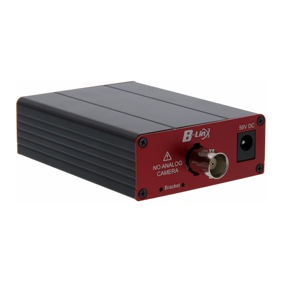
Page 5: Hardware Overview
1.4. Hardware Overview Right 56V DC NO ANALOG CAMERA Bracket Bracket Hole DC Power Jack PoE ON/OFF Switch PoE-ON (Transmitter model only) (Transmitter model PD-AUX (Receiver model only) only) Left ETHERNET PoE-ON Data-Link Join-Link Power Join Bracket Bracket Hole Join Button RJ45 Status LED Indicator Quick Installation Guide —... -
Page 6: Product Installation Guide
1.5. Product Installation Guide 1. Set the IP address on the camera following the instruction manual of the camera. h If the camera IP is automatically assigned (DHCP, etc.), there is no need to set the camera IP separately. 2. Connect BNC of the coaxial cable to each Transmitter/Receiver. 3. -
Page 7: Network Password Change
1.7. Network Password Change All EPoC products have the same network password on factory default to support plug & play between EPoC products. In case of multiple 1:1 connections, It is possible to avoid network interference by setting password of each group. 1. -
Page 8: Led Indicators
1.8. LED Indicators Indicator Color Function PoE-ON PoE Output Status (Transmitter model only) PD-AUX PoE Input Status (Receiver model only) Data-Link Blinks when transmitting Ethernet data Join-Link EPoC products connected Power 56VDC or PoE Input connected 1.9. Specification Model Transmitter Receiver 1 x 75Ω... -
Page 9: Caution
1.10. Caution • Please install the device following the installation guide. • Do not touch the device and cable with wet hands. • Keep away from moisture and shock. • Do not install near any heat sources such as radiators, heat registers, stoves or other apparatus that produce heat. -
Page 10: Pre-Field Verification
2. Pre-field verification 2.1. Check transmission line 2.1.1. Transmission line type EPoC (Ethernet over Coax) Applicable █ Coaxial cable 2-Wire 3C, 5C, 7C, 10C, RG58, RG59, UTP cable RG6, RG11, KX6, KX100, etc. EPoC Extender + Ethernet over IAM-4MU1001M0A Coax Extender Pre-field verification —... - Page 11 2.1.2. Check whether the cable is disconnected / shorted Test cable opens █ 1. Make a short the conductor and shield of the one side of the coax. 2. Take the testing probe and connect its cords to the specific ends of multimeter (red positive into the ‘+’ marked jack and black negative into the ‘COM’...
- Page 12 Cable Connection Precautions █ • Be sure to use dedicated connector when connecting cables. • It is not recommended to mix different types of cables. - When 50Ω and 75Ω cable are used in combination or 50Ω BNC is applied to 75Ω cable, the impedance between the lines is unmatched and this could affect performance of the device.
- Page 13 2.1.3. Cable distance Ethernet over Coax (EPoC) products have different Ethernet and PoE transmission distance depending on the product lineup. Check the maximum transmission distance between the transmitter and receiver in advance. PoE distance by available wattage to end-device (e.g. Single port product) █...
- Page 14 2.1.4. Identify loop resistance • By measuring the loop resistance of the cable, it is possible to check the condition and the quality of the cable used for power transmission function of the EPoC device in advance. 1. Make a short the conductor and 2.
-
Page 15: Check Grounding And Potential Difference
2.2. Check grounding and potential difference EPoC equipment is basically grounded through the power cord of the adapter, so there is no need to ground separately. However, EPoC equipment supports PoC (Power Over Coax) function and the transmitter is powered by the power source connected to the receiver and the end-device is powered by the transmitter through the PoE output feature. -
Page 16: Power Supply Availability
2.4. Power supply availability EPoC equipment supports PoC (Power over Coax), so that the transmitter and the end-device (e.g. camera) are powered by receiver. When installing multiple cameras over one cable with daisy chain configuration or PTZ camera with high power consumption, it is possible to configure by putting an additional power adapter (48 ~ 57VDC) on the transmitter. -
Page 17: Equipment Installation Guide
3. Equipment Installation Guide 3.1. Selection of installation equipment 3.1.1. EPoC Solution Network Security IP Video Surveillance █ EPoC devices allow the coaxial cables from existing analogue CCTV system to be re-used for network camera connection. Reusing existing coax for IP cameras can cut installation costs and save installation time significantly. EPoC devices will even provide 60W power over existing cable and outputs PoE to cameras, it would be sufficient power for up to 4 cameras operation in DAISY CHAIN CONFIGURATION. - Page 18 Network Extension █ Extended distance with PoE EPoC devices provides high speed & long distance Ethernet connectivity via various cables such as Coax, UTP 4 pair cable, even UTP 1 pair cable, etc. With long distance transmission feature, EPoC devices make to overcome 100 distance limitation of the general network configuration in a simple and easy way.
-
Page 19: Transmission Rate / Poe Output
3.2. Transmission rate / PoE output • Transmission rate(Mbps) by product configuration Daisy Chain Distance 200m 600m 1,200m 1,800m 2,400m • PoE output(W) by product configuration Daisy Chain Distance 200m 300m 400m 500m 700m Equipment Installation Guide — 18... -
Page 20: Poe On / Off Setting
3.3. PoE On / Off Setting EPoC transmitter has PoE On / Off switch. When connecting with non-PoE equipment, PoE The switch must be set to Off. The factory default setting of the PoE On / Off switch is OFF. Therefore, when installing transmitter with PoE devices, the PoE switch must be set to On for power supply. -
Page 21: Joining (Network Grouping Password Setting)
3.4. Joining (Network Grouping Password Setting) EPoC devices support Joining (Network Grouping Password Setting) function. When cross-talking issue occurs between devices, communication between products can be encrypted with joining function for reliable communication without interference problem. All EPoC devices have the same network password on factory default to support plug & play between EPoC devices. In case of multiple 1:1 connections, It is possible to avoid network interference by setting password of each group. - Page 22 2. [Clear password] Press the Join button of EPoC Rx and Tx (one by one) for more than 15 seconds and Check that the blue power LED turns off and on again. Hold the Join button for at least 15 seconds 3.
- Page 23 3.4.2. 1: N Join method between EPoC products (password setting between products) 1: N Joining █ 1. [Power on equipment] After connecting Coax (BNC) or UTP or 2-wire between EPoC Rx Tx, check that Power LED is blue. 2. [Clear password] 2-1.
- Page 24 3. [Joining] 3-1. Press and hold each Join button of the Tx and Rx for 1 ~ 2 seconds and after approx. 7 seconds, Power LED turns off and lights up Check the BNC (Join) LED lights up in green. 3-2.
- Page 25 3.4.3. 1: N Join method between EPoC products (when setting password between products) Components at Join █ • EPoC Rx Tx products • 56V or 57V VDC Power Adapter (GM60-550120-F recommended • Coaxial cable 1m • File clips (everything else within 2mm diameter) What to do if joining fails █...
-
Page 26: Daisy Chain Connection
3.5. Daisy Chain Connection • The EPoC product supports a 1: N Daisy Chain configuration with 1: 2 or 1: 4 BNC Splitter (T-type BNC connectors) and It is possible to connect multiple transmitters to one receiver over 1 line of the coax or UTP 4 pair or 2 wire. •... -
Page 27: Product Power Supply (Dc Adapter / Poe)
3.6. Product power supply (DC adapter / PoE) • EPoC device supports 12 ~ 57VDC input or PoE + (IEEE802.3af / at) input for product operation and PoE output. (Power over Cable) • EPoC Device supports PoC (Power over Cable) function, so that the transmitter and camera are powered by the power from DC power supply connected to the receiver. -
Page 28: Led Operating Status
3.7. LED operating status 3.7.1. LED status Indicator Color Function PoE-ON PoE Output Status (Transmitter model only) PD-AUX PoE Input Status (Receiver model only) Data-Link Blinks when transmitting Ethernet data Join-Link EPoC products connected Power 56VDC or PoE Input connected 3.7.2. -
Page 29: Grounding And Potential Difference
3.8. Grounding and Potential Difference EPoC device is basically grounded through the AC power cord of the adapter, so there is no need to ground separately. If there is a potential difference between the camera(specially metal housing camera) and ground (metal surface), PSE of the EPoC transmitter cannot detect camera’s PD correctly and PoE output will not operate properly. -
Page 30: Troubleshooting Faq
4. Troubleshooting FAQ 4.1. EPoC transmission equipment Problem Action Looking at the features, First, when replacing analog cameras with high-resolution IP camera, you can use the existing Coaxial cable without any special construction. Second, you can supply PoE power or 12VDC to IP camera. As a result, there is no additional power wiring work when installing IP cameras. - Page 31 Problem Action Basically, only 1 power adaptor is used on the Rx EPoC (or Tx EPoC). When power is applied to Rx EPoC only with 48~57V adapter, Tx EPoC consumes some power from 48 ~ 57VDC transmitted by Rx EPoC through the cables and outputs remaining power by PoE or 12VDC.
- Page 32 Problem Action In case of the EPoC devices which are not support PoE input feature. Is it possible to connect the Rx EPoC to Yes. Theoretically, there is no problem, but it is recommended to connect NVRs via the PoE switch or hub in the with a general switch or hub rather than a PoE switch or hub.
- Page 33 Problem Action Tx, Rx EPoC network passwords are different from each other and communication is impossible, so a separate joining procedure is required. 1. How to Join 1) Connect BNC or RJ45(using BTE-04) between Tx and Rx EPoC, and when Power LED is blue 2) Press and hold Join button of Tx, Rx EPoC for 2 seconds.
- Page 34 Problem Action Check the power LED status of Tx EPoC. If the blue LED is not turn on, it could be for transmission media and distance, or a faulty DC power input. If the blue is on, check the PoE switch status next.
- Page 35 VIDEOR E. Hartig GmbH Exclusive distribution through special- ised trade channels only. VIDEOR E. Hartig GmbH Carl-Zeiss-Straße 8 63322 Rödermark/Germany Tel. +49 (0) 6074 / 888-0 Technical changes reserved Fax +49 (0) 6074 / 888-100 www.videor.com...
Need help?
Do you have a question about the IAM-6MC1001MTA and is the answer not in the manual?
Questions and answers