
Subscribe to Our Youtube Channel
Related Manuals for IONODES ATOMAS-MINI


Summary of Contents for IONODES ATOMAS-MINI
- Page 1 DOCUMENT APPROVED FOR GENERAL DISTRIBUTION ATOMAS-MINI User Manual Version 1.5 IONODES INC. Laval, Québec, Canada www.ionodes.com...
-
Page 2: Table Of Contents
Table of Contents BEFORE YOU BEGIN ............................4 ATOMAS-MINI ..........................4 BOUT THE ................................. 5 ARTS HARDWARE INTEGRATION.......................... 6 ........................6 EMPERATURE ONSIDERATIONS ATOMAS-MINI ..............................7 ............................7 INOUT ESCRIPTION Connector Part Numbers ..........................9 J1 – Audio & I/O Signals ..........................9 J2 - 10 Pin Micro SD / SD Connector ...................... - Page 3 Configuration / Audio Out ........................... 45 Configuration / Serial Ports ........................46 Configuration / Integration ......................... 47 Configuration / Recording ........................... 48 Configuration / User Accounts ........................52 PTZ P ............................53 RESET OURS Configuring Preset Tours ..........................53 Using PTZ Preset Tours ..........................54 ..............................
-
Page 4: Before You Begin
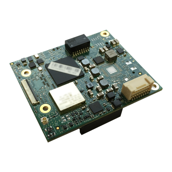
Before you begin About the ATOMAS-MINI The ATOMAS-MINI single port OEM encoder module delivers high quality H.264 video encoding to the video surveillance market. It is an embedded, high-performance digital video OEM encoder module designed for integration into HD cameras or other video capture products. -
Page 5: Parts List
Note: The product serial number label helps the Ionodes product support team identify your device and its factory configuration in the event that your Ionodes product or its components require service. The label is attached on the underside of the PCBA module. -
Page 6: Hardware Integration
In addition, a slight clearance around the board’s edge can also be used for extrusion-type enclosures. When integrating the ATOMAS-MINI into a product design, position the module to allow for air circulation around the board in order to maximize the chances of heat dissipation. -
Page 7: Atomas-Mini
ATOMAS-MINI Pinout Description Figure 1 - Top Side Page 7 of 71... - Page 8 Figure 2 - Bottom Side Page 8 of 71...
-
Page 9: Connector Part Numbers
Connector Part Numbers ATOMAS-MINI-LVDS / Module J1 – SAMTEC / TFC-115-32-F-D J2 – TE Connectivity / 1-1734839-0 J3 – MOLEX / 5041891670 J7 – SAMTEC / TFC-110-32-F-D J8 – SAMTEC / CLP-103-02-G-D J14 – Kel / USL00-30L ATOMAS-MINI-YUV / Module J1 –... - Page 10 RS-485 RX+ PWR SRC 1 For internal purposes only. DO NOT USE. RS-485 RX- DEBUG Serial Port The debug port (DEBUG TX/RX) is for internal use by IONODES and should be left disconnected on production designs. Page 10 of 71...
- Page 11 (such as a PTZ controller). J1 provides RS422/485 access to the device’s serial port; TTL levels for this same serial port are accessible via UART0 pins (TX and RX) on connector J1. To connect a serial controller to an ATOMAS-MINI using RS-422/485 4-wire configuration, use the following steps: 1.
- Page 12 RST / FACT DFLT Signal The ATOMAS-MINI provides a reset signal input. To trigger the reset signal, short the RST pin to the GND. The reset signal can be used to perform a device reboot, or to perform a complete reset to factory default settings of the device’s configuration parameters.
- Page 13 Page 13 of 71...
-
Page 14: J2 - 10 Pin Micro Sd / Sd Connector
MEZ DRY IN Signals The ATOMAS-MINI provides two (2) input pin signals, MEZ DRY IN1 and MEZ DRY IN2, for eventing purposes. To trigger an input pin (closed stated), you must connect the appropriate MEZ DRY IN signal with the provided GND located on connector J1. To set the open state, leave the input floating. - Page 15 (5V) Power Input Range The power input range on the ATOMAS-MINI-LVDS device is 7VDC to 12VDC. The power input range on the ATOMAS-MINI-YUV device is 7VDC to 14VDC. Note: IONODES has an optional PoE module (power-over-Ethernet) which can be used to add PoE support for your ATOMAS-MINI design.
-
Page 16: J4 - Parallel Video Interface
J4 – Parallel Video Interface AVX / 04-6296-045-931-846+ Pin No. Name Comments I2C Serial Bus Clock I2C Serial Bus Data I/O XRST System Reset DO NOT CONNECT. DO NOT CONNECT. DO NOT CONNECT. DO NOT CONNECT. DO NOT CONNECT. DO NOT CONNECT. Digital Video V-Active Signal Digital Video H-Active Signal Digital Video Data (Luminance Parallel Data0) - Page 17 Power Supply (3.3V) VDD_33 Power Supply (3.3V) Note: Available on ATOMAS-MINI-YUV only. Note: The HD sensor connector has been designed to be directly compatible with SONY’s FFC ribbon cables used with their FCB Micro Series cameras. Note: The following cable is recommended for connectivity between connector J3 and the SONY FCB-MICRO cameras: MOLEX P/N: 0150150245: CABLE FLAT FLEX 45POS .3MM 2"...
-
Page 18: J7 - Network & Power Outputs
5V DC Power Output (max. 1.5A) 3.3V Out 3.3V DC Power Output (max. 350mA) DC Power Output for FAN control. Optional, please consult IONODES for more info. (5V) HEATER DC Power Output for HEATER control. Optional, please consult IONODES for more info. (5V) VRTC DC Power Input for RTC. -
Page 19: J8 - Internal Port
4 wires for 10/100 Base-T network connection, please connect the appropriate network connection pins to your RJ45 connector or wiring. Network status LED pins are also accessible if needed. Note: Magnetics are included on the ATOMAS-MINI, J7 can therefore be connected directly to network switching equipment. -
Page 20: J14 - Lvds Video Interface
J14 – LVDS Video Interface Kel / USL00-30L Pin No. Name Comments LVDS DATA3 + LVDS DATA3 - LVDS CLK + LVDS CLK - LVDS DATA2 + LVDS DATA2 - LVDS DATA1 + LVDS DATA1 - LVDS DATA0 + LVDS DATA0- CAM UART TX Connects to camera’s TxD. - Page 21 RESET OUT Reset: Low (GND) Normal: Open (1.8V) Note: Available on ATOMAS-MINI-LVDS only. Page 21 of 71...
-
Page 22: Understanding Led Status
Software watchdog is rebooting the appliance – LED is flashing rapidly red Firmware update in progress – LED is flashing slowly red/green Note: Under normal operation, the ATOMAS-MINI takes up to 1 minute and a half to boot Page 22 of 71... -
Page 23: Atomas-Mini-Sdio
The ATOMAS-MINI-SDIO breakout card is an optional module provided by IONODES which provides microSD storage support to your ATOMAS-MINI module. The ATOMAS-MINI-SDIO module is provided as part of the ATOMAS-MINI-SDIO-KIT part number which also includes a cable required to connect the ATOMAS-MINI-SDIO to the ATOMAS-MINI module. Pinout Description... -
Page 24: J1 - Micro Sd Socket
J1 – Micro SD Socket In order to use the micro SD functionalities with the ATOMAS-MINI, make sure to use a 2GB to 64GB micro SD of class 6 or above. You must also make sure the card is formatted in FAT32 or EXT3. -
Page 25: System Configuration
System Configuration For initial set-up, the ATOMAS-MINI needs to be configured prior to using it with your network video management system. In most cases, only network configuration will be required. Since not all ATOMAS-MINI parameters can be controlled via networked video management systems, advanced parameters may need to be set-up as well through the ION specific software tools. - Page 26 Once your device is installed on your network and powered up, launch ICT from any computer on the network and the following window will be displayed: The ICT supports 2 ways to discover a device. The first way doesn’t need any configuration and uses the Bonjour discovery protocol.
- Page 27 To configure the Unicast Discovery, add one or more IP address ranges. The Unicast Discovery tries to reach a device at a specific IP address in the configured ranges. The discovery can be a long process if the range of IP addresses is huge and the device is at the end of the range. To accelerate the discovery, add several small ranges of IP addresses.
- Page 28 If no DHCP server was able to assign an IP address to an ATOMAS-MINI, it will appear in the ICT device list with an APIPA address (169.254.*.*). If an ATOMAS-MINI displays an APIPA address it must be configured with a valid IP address before it can be remotely configured by selecting the ‘’Assign IP address’’...
-
Page 29: Using The Atomas-Mini Web Application
Once the IP information is set, the Silverlight web application served by the ATOMAS-MINI can be launched from the ICT or directly in your web browser by typing the device’s IP address in the address bar. You can start to use your networked video management system for final system configuration or you can configure advanced parameters using the ATOMAS-MINI’s web based... -
Page 30: System Status
System Status Upon successfully logging into the web interface, a System Status screen will be displayed. The system status screen shows general devices health status as well as firmware version, system uptime, system average CPU utilization and internal temperature. The System Status page will also display the various features (e.g. -
Page 31: Configuration / System
Configuration / System Under the Configuration section, select the System tab to perform the following operations: View product model information, current firmware version and serial number. Specify a custom name; this name can be used by third-party software to display a friendly name for the device Page 31 of 71... -
Page 32: Configuration / Date Time
Configuration / Date Time Under the Configuration section, select the Date Time tab to perform the following operations: Set the timezone in which the device is operating. Manually set the current date and time for the device’s internal clock. Page 32 of 71... -
Page 33: Configuration / Network
API Selection – Enable the required Network APIs. Enable PSIA or GENETEC API depending on which VMS platform you intend to use with the device. Disabling any unrequired APIs will accelerate boot time. Note that the IONODES ION API and OnVIF API’s are always enabled. - Page 34 SNMP – Modify SNMP settings to match with any SNMP software you wish to use for monitoring the device. RTSP Configuration – Change the device’s RTSP configuration RTSP Server Port – TCP port used by the RTSP server. Session Timeout – Configure timeout in seconds for RTSP keep-alive. Authentication mode –...
-
Page 35: Configuration / Video In
Configuration / Video In Under the Configuration section, select the Video In tab to perform the following operations: Preview – This section allows you to view a thumbnail preview image of the camera’s video input. This feature requires that the MJPEG encoder be enabled on the camera, otherwise a placeholder image will be shown indicating “No Video Input”. - Page 36 Note: 1080p50/60 resolutions will take most of the resources of the internal processor, we therefore recommend that motion detection, VBR aggressiveness, recording and noise reduction be disabled under this configuration. Wide Conversion– Set the desired behaviour when the video input requires rescaling;...
- Page 37 We do not recommend changing default values unless you have a good understanding of the H.264 compression process. Intrat Interval – Defines the GOP size VBR aggressiveness is unique to IONODES encoders and proposes various levels (disabled to aggressive) of motion triggered rate control. The more aggressive the setting, the more variation motion will have on the rate control.
- Page 38 Destination Port: Network port where to send the video. This value must match the port value in the ION-Decoder. Once all the settings have been set, click on Save at the bottom of the page to apply them. The ATOMAS-MINI then creates or updates the connection as needed. Page 38 of 71...
- Page 39 PTZ – This section allows you to configure PTZ control behaviour. Enabled – allows you to enable PTZ support on this encoder module. Camera PTZ Id – Logical ID associated to the PTZ controller connected to this encoder module. Control Protocol – PTZ protocol used by the PTZ controller connected to this encoder module.
- Page 40 Override Presets – Allows you to override a specific PTZ preset. Following the selected protocol, a fixed set of presets can be configured. But, depending of the PTZ controller, more presets can be available. To be able to call a preset over the official protocol preset range, a preset can be overridden to call an extended preset id.
- Page 41 Text Overlay – This section allows you to add text overlays to encoded video streams. Note that these strings will be embedded into the images streamed out of the device. See section 5.4 for details on the automatic text options. ImmerVision Enables 2.0 Marking –...
- Page 42 Motion Detection – This section allows you to configure motion detection regions of interest. Most VMS platforms will control motion detection parameters and thus would not require setting anything within the web interface. For more details on configuring motion detection, see section Error! Reference source not found.5. Page 42 of 71...
- Page 43 Privacy Zones – This section allows you to configure up to 16 privacy zones JPEG Upload – This section allows you to configure JPEG Upload functionality. See section 5.5 for more details Page 43 of 71...
-
Page 44: Configuration / Audio In
Configure audio input compression parameters Configure point to point audio connections (up to three) for creating persistent audio streams from the encoder to a network endpoint. This feature is particularly useful when combined with an IONODES decoder (ION-R100) Page 44 of 71... -
Page 45: Configuration / Audio Out
Under the Configuration section, select the Audio Out tab to perform the following operations: Configure audio output parameters Configure a point to point audio connection for receiving a persistent audio stream from a network endpoint. This feature is particularly useful when combined with any IONODES decoder Page 45 of 71... -
Page 46: Configuration / Serial Ports
Serial Port 1 Point to Point – This section allows you to configure a point to point serial port connection for creating a persistent serial port connection with a network endpoint. This feature is particularly useful when combined with an IONODES decoder (ION- R100). -
Page 47: Configuration / Integration
Configuration / Integration Under the Configuration section, select the Integration tab to perform one of the following operations: Enable HikVision iVMS OnVif video analytics – This enables the integration with the HikVision iVMS by leveraging the OnVif Video Analytics feature (more specifically the VideoCellMotionDetectorModule);... -
Page 48: Configuration / Recording
Configuration / Recording Under the Configuration section, select the Recording tab to enable the Media Recorder to store video on the MicroSD card. This section allows you to perform the following operations: Enabled – Enable the Edge Recording General Global settings applied to the recorder module. NVR Detection Mode –... - Page 49 Maximum File Duration – Recorded file duration. When maximum file duration is reached, a new one will be created Maximum File Size – Recorded file size. When maximum file size is reached a new one will be created Note: The above rule is applied when one of the two condtions is reached. Grooming The grooming module manages the rules to apply during the recording in order to preserve the desired ratio of recorded files versus the empty space.
- Page 50 Continuously recording mode Record Alarms – Allow the recorder to record the triggered alarms in the system as well as the video file. Alarms will be recorded in a separate track in the ASF file. Connection with the server is lost – Triggered when the connection with the VMS / Server is lost On demand –...
- Page 51 an on-demand recording. On-Motion event – Starts recording when a motion event is triggered and Stops recording when no motion is detected. Custom alarm – Start / Stop recording when an ION API custom alarm request has been received. When selected, a unique identifier is generated and must be used when sending the ION API request.
-
Page 52: Configuration / User Accounts
Configuration / User Accounts Under the Configuration section, select the User Accounts tab to perform the following operations: Select the web interface’s authentication method. A dual passphrase is made available for additional security. Manage user accounts which have access to the device. The user account roles are defined as follows: The User role allows access to viewing only, no permission to change any set-tings The Poweruser role allows access to live video and changing any setting aside from the... -
Page 53: Ptz Preset Tours
PTZ Preset Tours Configuring Preset Tours In IONODES devices, video inputs connected to PTZ cameras also support up to 8 preset tours. The PTZ preset tours can be set up from the PTZ sub-section of the video input configuration page: To configure a PTZ preset tour, add or remove presets as needed. -
Page 54: Using Ptz Preset Tours
The tour also automatically stops if the PTZ camera is moved manually by the user. After such an occurrence, the tour can be restarted by clicking on the Start button again. Note: Please see Appendix B for details on the various scenarios for the PTZ integration with the Atomas-Mini Page 54 of 71... -
Page 55: Text Overlay
Text Overlay The text overlay also includes special codes to display dynamic information. These special codes are as follow: Display the date and time (hh:mm:ss) in local time. Display the date and time (hh:mm:ss) in UTC time. Display the time (hh:mm:ss) in local time. Display the time (hh:mm:ss) in UTC time. -
Page 56: Motion Detection
Motion Detection Motion detection configuration can be simple or complicated depending on the scene and the desired detection behaviour. Let’s explore an example to better understand how each setting should be configured based on scene and behaviour requirements. In our example, we wish to trigger a motion detection event when a vehicle appears within an outdoor scene. -
Page 57: Notifications
Video recording based on motion detection will discard any recorded sequence of less than 5 seconds. Please ensure that your motion on / off scenarios are adequate for timespans of 5 seconds or more. Notifications The notification feature allows you to create rules which will trigger email notifications under certain conditions. -
Page 58: Recording
2. Modify any rule parameters in the right window. 3. Click the Save button to save changes. To delete a notification rule: 1. Select the notification rule from the list. 2. Click the Delete button. 3. A confirmation window will appear to confirm deletion. Click Yes. Available notification rule parameters are as follow: Name: friendly name of the notification rule. -
Page 59: Live Viewer
From the recorded clips list, you can select one or more clips to download, delete, lock or unlock. Live Viewer The Live Viewer pager allows you to play a mjpeg video as well as have access to the PTZ control. Page 59 of 71... -
Page 60: Inputs / Outputs
Inputs / Outputs As described in section 3.1.2.5, the Atomas – Mini provides a digital I/O for control tasks purpose. The Inputs / Outputs page allows you to see the status of the digital I/O when they are connected to a relay switch. Maintenance The Maintenance page allows you to grab the system information (sysinfo) file, perform an update, identify current device, reboot the unit and perform a factory reset. -
Page 61: Performing A Firmware Update
Performing a Firmware Update This section describes how to update your ATOMAS-MINI to newer firmware versions from the web application. 1. Navigate to your device’s web application using your favorite web browser. 2. Click on the Maintenance tab. 3. Click on the Update button. You will be asked for the firmware update file; please select the .iof file which was provided by IONODES. - Page 62 Status LED is flashing red-green. Firmware update complete. (100%) Page 62 of 71...
-
Page 63: Batch Firmware Update
Batch Firmware Update This section describes how to perform a batch update of multiple ATOMAS-MINI devices to newer firmware versions from the ICT. The batch firmware update works by starting a firmware update session. Only one session at time is allowed and only 20 devices can be selected by session. - Page 64 To start a firmware update session, choose the “.iof” file corresponding to the new firmware by clicking to the “Select File …” button. Once selected, click to the “Start” button. Page 64 of 71...
- Page 65 Once started, the “Firmware Update Session” window shows the progress of the firmware update. This window can be closed at any moment without losing the current session. If closed, the progress of the current session can be followed by reopening the “Firmware Update Session”...
-
Page 66: Annex A - Troubleshooting Guide
Make sure the GREEN LED on the RJ45 connector is lit. If it is not lit, verify the network connectivity with the network switch. Dynamic discovery of the ATOMAS-MINI requires multicast networking to be supported by your network and switch equipment. (Bonjour protocol) - Page 67 Validate your network firewall is not blocking your video stream. Use Live Viewer (require mjpeg encoder being enabled) to make sure the Atomas is currently streaming Page 67 of 71...
-
Page 68: Annex B - Ptz Integration
Annex B Annex B – PTZ Integration This section describes the different PTZ scenarios that can be utilized with the Atomas-Mini. Scenario 1 Atomas Atomas Video Transparent TCP (binary data) Camera Block Cam UART Ex: Visca PtzManager OnVif UART PTZ Controller... - Page 69 Scenario 2 Atomas Atomas Video Camera Block Transparent TCP (binary data) UART PtzManager UART PTZ Controller PelcoD ION API Genetec API Camera block connected to the video input port (YUV, LVDS, HD-SDI, MIPI) PTZ controller connected to the serial port Requirements: No sensor selection or custom from the web management interface: Con- figuration / Video In / General / Select Sensor Requirements: PTZ protocol selection from the web management interface: Configura-...
-
Page 70: Annex C - Statement Limited Warranty
The warranty period for an ATOMAS-MINI is a specified, fixed period commencing on date of billing by Ionodes for the Product. If a valid proof of billing cannot be found, the warranty may be void by Ionodes Inc. or measured from the date the ATOMAS-MINI has shipped from a Ionodes De- pot center based on its serial number. - Page 71 "how–to" questions and those regarding ATOMAS-MINI set–up and installation, will be provided WITHOUT WARRANTIES OF ANY KIND. For more information, please contact our technical support team: • Call: 450.696.1060 or 1‐844-696-1060 (North America Toll Free) • Send an email to: support@ionodes.com...
Need help?
Do you have a question about the ATOMAS-MINI and is the answer not in the manual?
Questions and answers