
Subscribe to Our Youtube Channel
Related Manuals for IONODES ION-R100


Summary of Contents for IONODES ION-R100
- Page 1 DOCUMENT APPROVED FOR GENERAL DISTRIBUTION ION-R100 User Manual Version 1.10 IONODES INC. www.ionodes.com...
-
Page 2: Table Of Contents
Table of Contents BEFORE YOU BEGIN ..........................3 ION-R100 .......................... 3 BOUT THE ............................4 ARTS HARDWARE INSTALLATION ....................... 5 ........................5 QUIPMENT NSTALLATION CONNECTIONS ............................6 ............................6 ANEL ............................7 RONT ANEL SERIAL PORT CONNECTIVITY ......................10 UNDERSTANDING LED STATUS ......................12 DEVICE CONFIGURATION ........................ -
Page 3: Before You Begin
H.264/MJPEG video to an analog (SD) or HDMI (720p/1080p) display. Embedding support for networked API’s, the ION-R100 can be integrated into a networked video management system allowing for centralized monitoring and management in a scalable and expandable IP surveillance system. -
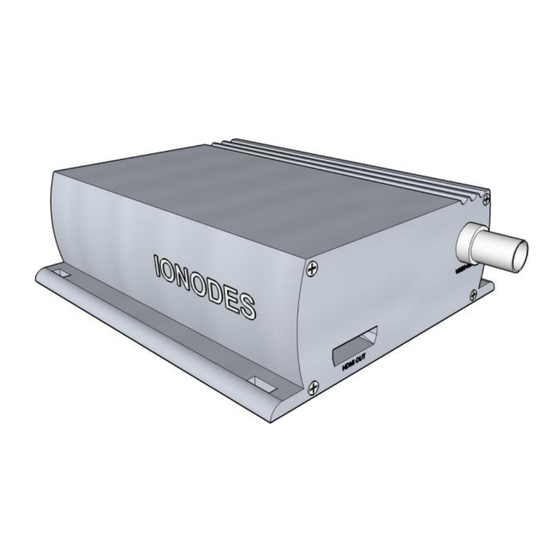
Page 4: Parts List
Note: The product serial number label helps the IONODES product support team identify your device and its factory configuration in the event that your ION-R100 or its com- ponents require service. The label is attached on the underside of the enclosure. -
Page 5: Hardware Installation
2 Hardware Installation 2.1 Equipment Installation The ION-R100 can be placed on a flat surface, such as a desktop, or mounted via the available mounting holes. When installing the ION-R100, position the unit to allow for cable clearance at the front and rear of the unit. -
Page 6: Connections
ION-R100 3 Connections Familiarize yourself with the ION-R100 front and rear panels before connecting any equipment to the unit. The ION-R100 offers an analog video output, an HDMI video output, and associated I/Os and audio connections. 3.1 Rear Panel •... -
Page 7: Front Panel
ION-R100 – User manual 3.2 Front Panel Terminal Bloc Header • Terminal Bloc Header This header connector is used to connect the supplied Terminal Bloc Socket which provides the interface to serial port, I/O and power connections. Below is a detailed view of this Terminal Bloc Socket: Relay Output Digital Input Pins #1 &... - Page 8 • ETHERNET / PoE This is the ION-R100 network port. Please use a straight RJ45 (cat. 5 or 6) network cable. The ION-R100 accepts a Power-Over-Ethernet (PoE) compliant power source if needed. Page 8 of 40...
- Page 9 ION-R100 – User manual • RESET The reset button can be used to perform a hardware reset, or to perform a complete reset to default settings of the device’s configuration parameters. Rebooting the appliance: press and release quickly the reset button with the tip...
-
Page 10: Serial Port Connectivity
These protocols are standards for binary data exchange between DTE and DCE equipments. To connect serial equipment to an ION-R100 using RS-422/485 4-wire configuration, use the following steps: 1. Connect twisted pair cables to the Terminal Bloc Socket located on the front panel of the device. - Page 11 ION-R100 – User manual To connect serial equipment to an ION-R100 using RS-485 2-wire configuration, use the following steps: 1. To create the negative data signal, please connect Rx- and Tx- pins together on the Terminal Bloc Socket. 2. To create the positive data signal, please connect Rx+ and Tx+ pins together on the Terminal Bloc Socket.
-
Page 12: Understanding Led Status
Software watchdog is rebooting the appliance – LED is flashing rapidly red • Firmware update in progress – LED is flashing slowly red/green Note: Under normal operation, the ION-R100 takes up to 1-2 minutes to boot up. Page 12 of 40... -
Page 13: Device Configuration
6.1 Network Configuration By factory default, the ION-R100 is configured in DHCP. If you are not using a DHCP server it will automatically allocate itself an APIPA (Automatic Private IP Addressing) address in the range 169.254.0.1 to 169.254.255.254 with subnet mask 255.255.0.0. - Page 14 – User manual ION-R100 Identifying an IONODES device by flashing its LED (red/green) Applying batch firmware upgrade of all common IONODES devices Accessing a device’s web based management interface Once your device is installed on your network and powered up, launch the ICT from any computer located on the same network as the device.
- Page 15 ION-R100 – User manual To configure Unicast Discovery, add one or more IP address ranges. Unicast Discovery will attempt to reach a device at a specific IP address in the configured ranges. Discovery can be a long process if the range of IP addresses is large. To accelerate the discovery, add several small ranges of IP addresses.
- Page 16 – User manual ION-R100 If no DHCP server was able to assign an IP address to an ION-R100, it will appear in the ICT device list with an APIPA address (169.254.*.*). If an ION-R100 displays an APIPA address it must be configured with a valid IP address before it can be used on the network. Select the ‘’Assign IP address’’...
-
Page 17: Using The Ion-R100 Web Interface
ION-R100 – User manual 6.2 Using the ION-R100 Web Interface When accessing the device’s web interface, you will be asked to enter a username and password. The factory default user name and password are both ‘admin’. The following window will be displayed:... -
Page 18: Setting Up The Ntp Time Server
– User manual ION-R100 6.2.1 Setting up the NTP time server Under the Configuration section, select the Network tab and set the proper NTP server address under the NTP Configuration header. Click the Save button to apply the changes. Page 18 of 40... -
Page 19: Configuring Video Output Parameters
ION-R100 – User manual 6.2.2 Configuring video output parameters By default, the ION-R100 is configured to output video to the analog output port (BNC). Should you want to use high-definition HMDI output, you may change the Output Connector parameter to HDMI as shown in the image below. - Page 20 – User manual ION-R100 When the BNC output connector is selected, the desired Output Analog Standard (NTSC or PAL) can be selected as shown below to match your display monitor: When the HDMI output connector is selected, the desired Output Digital Format can be...
- Page 21 (BNC or HDMI). However, this is the only mode in which the ION-R100 will be able to decode an HD video source in resolutions up to 1080p30/720p60.
- Page 22 Note: Remember to click the Save button to apply any changes. Warning: Note that certain parameter changes (such as changing output modes from BNC to HDMI or vice versa) may require that you reboot the ION-R100 before the changes are applied. Page 22 of 40...
-
Page 23: Point To Point Connections
Video output parameters define the output type (BNC or HDMI) as well as decoder layout (1x1, 2x2 or sequence) of the ION-R100. Depending on the selected output layout, a set number of video stream decoders will be made available for configuration of point-to-point settings. - Page 24 – User manual ION-R100 For each video stream decoder, a set of parameters can be set and a point-to-point connection can be configured and enabled. The Decoder Starve parameter allows you to select the behavior of the video stream decoder when no H.264/MJPEG stream is being decoded for display.
- Page 25 ION-R100 – User manual For each video stream decoder, you may set-up a point-to-point connection with an H.264/MJPEG IP camera or video encoder. To enable the point-to-point connection, you must first select the appropriate Codec (H.264 or MJPEG) which matches the video stream source and check the Enabled checkbox.
- Page 26 (HTTP or RTSP), such as an IP camera or IP video encoder, and request the required video streams. When in passive mode, the ION-R100 does not establish any connection; it simply opens up a listening network port and waits for an incoming stream (RTP).
- Page 27 ION-R100 will create the point-to-point connection as configured. Note: IONODES performs regular testing on HTTP and RTSP streaming devices (IP cam- eras and encoders) to validate compatibility with the ION-R100. For a complete list of tested devices and associated URI’s, please contact IONODES or visit www.ionodes.com.
-
Page 28: Performing A Firmware Update
– User manual ION-R100 7 Performing a Firmware Update This section describes how to update your ION-R100 to newer firmware versions from the web application. 1. Navigate to your device’s web application using your favorite web browser. 2. Click on the Maintenance tab. -
Page 29: Batch Firmware Update
ION-R100 – User manual 7.1 Batch Firmware Update This section describes how to perform a batch update of multiple ION-R100 devices to newer firmware versions from the ICT. The batch firmware update works by starting a firmware update session. Only one session at time is allowed and only 20 devices can be selected by session. - Page 30 – User manual ION-R100 To start a firmware update session, choose the “.iof” file corresponding to the new firmware by clicking to the “Select File …” button. Once selected, click to the “Start” button. Once started, the “Firmware Update Session” window shows the progress of the firmware update.
- Page 31 ION-R100 – User manual If closed, the progress of the current session can be followed by reopening the “Firmware Update Session” window by clicking the button from the “Tools” toolbar. Once done, clear the current session from the “Firmware Update Session” window and restart a new session if needed.
-
Page 32: Quick Setup Guides
Quick Setup Guides 7.2 1x1 HDMI Layout w/ IP Camera This quick setup guide assists you in quickly setting up the ION-R100 for use as a spot monitor in 1x1 output layout on an HDMI display for use with an IP camera. - Page 33 ION-R100 and your IP camera. 18. You should now see video on the HDMI display. 19. Your ION-R100 is now configured in point-to-point with your IP camera and will re-initiate the video stream connection upon boot-up without any software assistance or human interaction.
-
Page 34: Hdmi Layout W / Four Ip Cameras
7.3 2x2 HDMI Layout w/ Four IP Cameras This quick setup guide assists you in quickly setting up the ION-R100 for use as a spot monitor in 2x2 output layout on an HDMI display for use with four IP cameras. - Page 35 19. You should now see video on the HDMI display in a 2x2 tiled layout. 20. Your ION-R100 is now configured in point-to-point with your four (4) IP cameras and will re-initiate the video stream connections upon boot-up without any software assistance or human interaction.
-
Page 36: Sequence Hdmi Layout W / Four Ip Cameras
7.4 1x1 Sequence HDMI Layout w/ Four IP Cameras This quick setup guide assists you in quickly setting up the ION-R100 for use as a spot monitor in 1x1 sequence output layout on an HDMI display for use with four IP cameras. - Page 37 19. You should now see video on the HDMI display in a full screen layout which will sequence through the four IP cameras at the configured time interval. 20. Your ION-R100 is now configured in point-to-point with your four (4) IP cameras and will re-initiate the video stream connections upon boot-up without any software assistance or human interaction.
-
Page 38: Annex A - Configuration Parameter Reference
– User manual ION-R100 Annex A – Configuration Parameter Reference 1. Video Output Configuration • Input Standard – The video standard allows you to select the video source as NTSC, PAL or 720p. • Brightness – The brightness filter allows you to set the black level of the video output. -
Page 39: Annex B - Troubleshooting Guide
Make sure the GREEN LED on the RJ45 connector is lit. If it is not lit, verify the network connectivity with the network switch. Dynamic discovery of the ION-R100 requires multicast networking to be supported by your network and switch equipment. (Bonjour protocol) -
Page 40: Annex C - Statement Limited Warranty
In case Ionodes or your reseller are unable to repair an Ionodes ION-R100, you can alternatively ask for a partial refund as far as justified by the reduced value of the unrepaired ION-R100 or ask for a cancellation of the respective agreement for such ION-R100 and get your money refunded.
Need help?
Do you have a question about the ION-R100 and is the answer not in the manual?
Questions and answers