Advertisement
Advertisement
Table of Contents

Subscribe to Our Youtube Channel
Summary of Contents for Microsensor MPM Series
- Page 1 MPM/MDM Transmitting Controller series operation manual V2.0...
-
Page 2: Table Of Contents
Contents 1.Introduction................... 1 2.Safety alarm...................2 3.Specification..................2 4.Outline construction................4 5. Electric connection................9 6. Calibration...................11 7.Installation................... 13 8.Communication protocol..............15 9.Responsibility..................17 Our company reserves the right to modify this manual due to product technique and process updates. If any information is modified, we will not make further notice. -
Page 3: Introduction
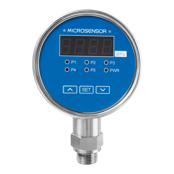
Thanks for selecting our products. Please read this manual carefully before operation. 1. Introduction MPM/MDM series transmitting controllers multi-functional instruments for pressure, differential pressure and level measurement and control which consists of MPM/MDM484C, MPM/MDM460, MPM460W, MPM/MDM484ZL. This series of products are all-electronic structure, which can measure, display and control on-site pressure, differential pressure and level. -
Page 4: Safety Alarm
Main and secondary screens are displayed simultaneously (484C has main screen only) Parameters setting and calibration by keys, easy to operate Analog output and RS485 interface (Modbus RTU protocol) available Max. 8-way control (460 series), high controlling accuracy ... - Page 5 Pressure: -100kPa…0kPa~10kPa…100MPa Differential pressure: 0kPa~50kPa…3.5MPa Overpressure: Level: 1.5 times FS Pressure: 1.5 times FS or 110MPa (min. value is valid) Differential pressure: static pressure ≤20MPa Power supply: 220V AC/110~370V DC/24V DC Output signal: Analog output: 4mA~20mA DC,0mA~10/20mA DC, 0/1V~5/10V DC Digital output: RS485 interface (Modbus RTU protocol) Environmental temp.: -10℃~60℃...
-
Page 6: Outline Construction
Secondary screen: 0.36” (460 series,484ZL series) Display range: -1999~9999 (red highlight LED) Digital part: sampling rate:10 times/s Relay qty.:1~5 (484C series,484ZL series) 1~8(460 series) Installation method: vertical and Horizontal mounting (MPM484ZL, MPM484C), submersible Protection: IP65:MPM460(W) and MDM460 display housing IP68:MPM460W sensor 4. - Page 7 SW27 φ6 M20×1.5 MPM484C Pressure Transmitting Controller φ27 G1/4 MDM484C Differential Pressure Transmitting Controller...
- Page 8 3-φ3.5 EQS φ116 (60) MPM484C Pressure Transmitting Controller (Horizontal mounting) b) MPM460, MDM460, MPM460W outline (175) φ27 M20×1.5 MPM460 Pressure Transmitting Controller...
- Page 9 (175) φ27 G1/4 MDM460 Differential Pressure Transmitting Controller ( 175) ( 175) φ 27 φ 18 SW36 SW48 M42× 1.5 φ 140 φ 26 φ 26 MPM460W Transmitting Transmitter MPM460WK Transmitting Controller...
- Page 10 c) MPM484ZL, MDM484ZL: terminal name cover plate SW27 φ6 M20×1.5 MPM484ZL Pressure Transmitting Controller terminal name cover plate φ27 G1/4 MDM484ZL Differential Pressure Transmitting Controller (vertical mounting)
-
Page 11: Electric Connection
3-φ6 EQS cover terminal name plate (68) φ168 MPM484ZL Pressure Transmitting Controller (horizontal mounting) Note: The pressure port dimension of controllers for vertical and horizontal mountings is the same. 5. Electric connection 5.1 MPM/MDM484C series 1, 2, 3: NC, NO and COM of relay 1; 4, 5, 6: NC, NO and COM of relay 2;... - Page 12 16,17,18: NC, NO and COM of relay 4; 7, 8: analog output terminal; 9,10: RS485 communication terminal; 11,12: AC/DC supply terminal; Notes: if the relay qty. is <2, there is no dotted box part (13~24). 5.2 MPM460, MPM460W, MDM460 inner electric connection Note: 1.
-
Page 13: Calibration
10,11,12: NO, COM and NC of relay 1; 4, 5, 6: NO, COM and NC of relay 2; 4, 5, 6: NO, COM and NC of relay 3; 1, 2, 3: NO, COM and NC of relay 4; 22, 23, 24: NO, COM and NC of relay 5; 7, 8, 9: NO, COM and NC of relay 2;... - Page 14 at measurement status; displays current parameter virtual value at setup status. In all states, the secondary display shows the current system status or limit value and cannot be changed individually. There are three keys on frond board, ▲, SET, and ▼ keys. 6.2 Key operation flow Relay 4 PASS...
-
Page 15: Installation
Note: 1.MPM484ZL has no“AL-6” to“AL-8F”; MPM484C has no“AL-6”to“AL-8F”,“F--L” and deputy display. All the information will be shown on main display if it has no deputy display; 2.Baud rate: 0/1200,1/2400,2/4800,3/9600,4/19200,5/38400,6/57600,7/115200; 3.Relay property: “0” indicates the lower limit alarm, “1” indicates upper limit alarm; 4. - Page 16 cut-off valve between flange connector and tube for easy installation and repair. There is one nylon protection cap on the pressure port of flush diaphragm type controllers. Please do not take off the cap to protect diaphragm if the user does not install. Please mount controller to pressure port M20X1.5 female, the screw depth should be less than 20mm (there should be a seal-ring on the type face).
-
Page 17: Communication Protocol
manifolds between controller and measuring point; pressure port G1/4 male’s length should be no more than 12mm, and sealed by seal cushion. Note: (1) process operation pressure should be no more than 20MPa. (2) the measured media differential pressure should not exceed upper limit pressure. - Page 18 Registe Register Register Name Name Name r add. add. add. 2nd limit 6th limit Add. 0001 0014 001C character value 3rd limit 6th limit baud rate 0002 0016 001D value character Real-time 3rd limit 7th limit 000F 0017 001E value character value Decimal...
-
Page 19: Responsibility
Analysis: byte number:0x04(4) 1:03 E9 (1001) 2:00 02 (2) Pressure value =1001*0.01=10.01 Note: The pressure value read is hexadecimal number, convert it to decimal number, divided by the decimal point value (0: divided by 1; 1: divided by 10; 2: divided by 100;...


Need help?
Do you have a question about the MPM Series and is the answer not in the manual?
Questions and answers