
Related Manuals for UEi Auto 2-2


Summary of Contents for UEi Auto 2-2
- Page 1 INSTRUCTION MANUAL Auto 2-2,AUTO 4-2 & AGA5000 ® 1-800-547-5740 • Fax: (503) 643-6322 www.ueitest.com • email: info@ueitest.com...
- Page 2 DESCRIPTION The UEI range of emission analyzers covering the models Auto 2-2, 4-2 and AGA5000 has been designed to be used on petrol, LPG or CNG powered engines*. All models measure carbon monoxide (CO), and unburnt hydrocarbons (HC), with Oxygen (O2) and carbon dioxide (CO2) added to four-gas models and nitric oxide (NO) included in five-gas variants.
-
Page 3: Table Of Contents
CONTENTS 1. ANALYZER LAYOUT AND FEATURES ..........1 1.1 Instrument features and keypad . - Page 4 7. STORING AND RETRIEVING DATA ..........18 7.1 Storing a Live Test .
-
Page 5: Analyzer Layout And Features
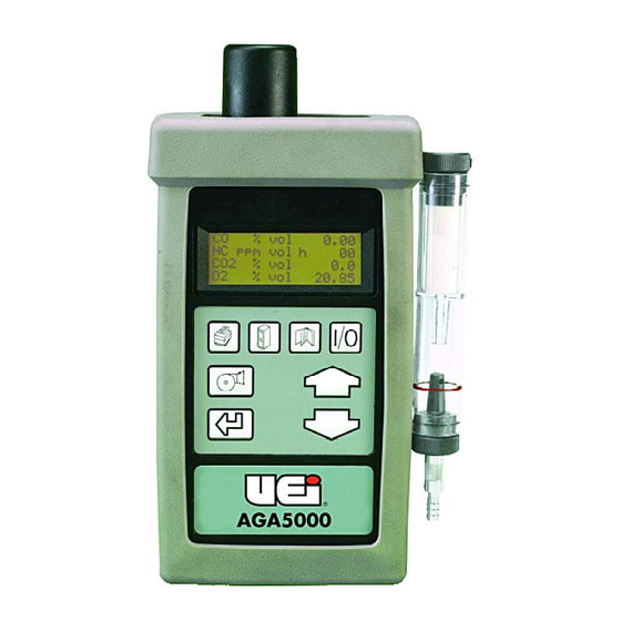
1. ANALYZER LAYOUT AND FEATURES 1.1 Instrument Features and Keypad Infra-red signal to printer NO sensor (standard on AGA5000 only) Gas Connection to Instrument External Particle Filter Battery Charger In-line Water Trap or 12 Volt (Keep clear of Adapter water at all times) Water Level Limit ON/OFF... -
Page 6: Instrument Layout (Rear)
Instrument Layout (Rear) 1.2 Instrument Layout (Rear) IR Emitter Exhaust Port Charger NOTE! Cover Socket Does Not Remove VEHICLE EXHAUST GAS ANALYZER Refer to Operators Instructions before use. Se reporter au Manuel d'Instructions avant utilisation. Vor Gebrauch Bedienungsanleitung beachten. Ver Instrucciones de Operacion antes de utilizar. Consultaire il Manuale di Istruzioni prima dell'uso. -
Page 7: Standard Probe Configuration
1.3 Standard Probe Configuration Probe Inlet Water Trap Connection Flexible Insertion Probe Probe Flexible Hose Line Exhaust Pipe Spring Handle Stainless Steel Shaft... -
Page 8: Safety Warning
2. SAFETY WARNING This analyzer extracts combustion gases that may be toxic in relatively low concentrations. These gases are exhausted from the top of the instrument. This instrument must only be used in well ventilated locations. It must only be used by trained and competent persons after due consideration of all the potential hazards. Protection Against Electric Shock (in accordance with EN 61010-1: 1993) This instrument is designated as Class III equipment and should only be connected to SELV circuits. -
Page 9: Normal Start Up Sequence
4. NORMAL START UP SEQUENCE 4.1 Every Time You Use The Analyzer BEFORE SWITCH-ON CHECK THAT: • The particle filter is dry and not dirty or damaged • The water trap and probe line are empty of water • All hose connections, etc. are properly made •... - Page 10 If YES is selected the following screen will be displayed : LEAK CHECK? REMOVE EXHAUST PROBE FIT PROBE SEAL THEN PRESS ENTER Fit the probe seal as detailed in Section 10.3 and press Once the test has PASSED remove the probe seal and press If the test fails see Section 10.3.
-
Page 11: Main Display Parameters
4.3 Main Displays The main display can be changed to show either 4 or 8 parameters at one time. Two options are available when 4 parameters are selected. • Line scroll mode allows you to customize the display to show the data you require. •... -
Page 12: Page Mode
LAMBDA ....0.000 NO PPM ..NOT FITTED TIME TO ZERO ....10 DEG C . -
Page 13: Sampling The Exhaust Gas
4.4 Sampling the Exhaust Gas Once the zero calibration and test procedures have been completed and the fuel has been selected (See Section 5.2.2) the probe can be inserted into the desired vehicle exhaust. Ensure the probe is inserted into the exhaust pipe so as to not allow air into the probe. The exhaust of a car can pulse, especially at low RPM, drawing air in causing bad readings, ensure the flexible probe is fully inserted and the clip attached to the exhaust pipe. -
Page 14: Taking An Oil Temperature Reading (Certain Analyzers Only)
4.6 Taking an oil temperature reading (Certain analyzers only) Connect the oil temperature probe to the instrument and check it reads ambient temperature. Turn off the vehicle engine. Remove the oil dip stick from the engine and set the depth of the probe to that of the dip stick using the stop. -
Page 15: Low Flow
4.8.1 Low Flow During sampling or at any time the pump is running the screen may display LOW FLOW. This is an indication of the following: • The particle filter needs replacing (a visual check is also necessary) • Probe or tubing is blocked. •... -
Page 16: Moving Through The Menus
5. MOVING THROUGH THE MENUS 5.1 Basic Operation From the MAIN DISPLAY vol . . .00.00 vol ..0000 vol ..00.00 vol ..20.90 Press MAIN MENU to access the MAIN MENU SELECT 3. -
Page 17: Menu Options And Settings
5.2 Menu Options and Settings 5.2.1 Main Menu The MAIN MENU consists of 4 sub menus which are shown below and detailed on the following pages. MAIN MENU SELECT 3. DISPLAY 2. UNITS 4. SETUP All sub-menus are accessed using and exited using keys move the cursor within a menu and allow parameters to be changed. -
Page 18: Units Menu
Allows the user to check the calibration of the analyzer using precision calibration test gases. It is CAL: recommended this is done every 3 months. Test gas is available from your service centre. The following can be performed in this menu: •... -
Page 19: Display Menu
Choose selections from Centigrade ˚C or Fahrenheit ˚F. (Certain analyzers only) TEMP: Changes the calculation used in the Lambda calculation. Change from LAMBDA to AFR. EFF: Formulas used in the analyzer are detailed in appendix B. Propane equivalence factor or n-hexane to propane ratio as set in the instrument. This is not a PEF: user variable parameter but is displayed for reference. -
Page 20: Set-Up Menu
NAME/PHONE 1-503-644-8723 'LEFT' USE STORE KEY The screen above shows the standard header setting with the cursor now shown underlining the U in UEI. By using any letter or number can be chosen. Once the correct character is displayed, use to move right to the next. -
Page 21: Printing Information - Optional Extra Only
6. PRINTING INFORMATION - OPTIONAL EXTRA ONLY Supplied as an accessory for the analyzer is an infra-red thermal printer. Read the manual supplied with the printer prior to operation. Connections to the analyzer are detailed below: • Infrared thermal printer - this does not require a cable to transmit the data but uses an infra-red (IR) link similar to a TV remote control. -
Page 22: Storing And Retrieving Data
7. STORING AND RETRIEVING DATA The Analyzer can store up to 255 emissions tests. Once stored, the data can be viewed on the display or downloaded to a printer. 7.1 Storing a Live Test While performing a test and viewing the data on the MAIN display access the STORE menu as follows: STORE MENU MODE : STORE... - Page 23 Move the cursor to Location and press . The cursor will move to the first digit of the first number, to select the correct digit and enter when correct. Repeat on the second digit until the location to view from is correct. Press to move the cursor to the second number, select the last location to view using the same procedure.
-
Page 24: Deleting Data
TIP: Stored and displayed with the data are actual time and date of the test. 7.3 Deleting Data To delete the data in stored memory press to obtain the STORE MENU (as above) STORE MENU MODE : DELETE Press to access the STORE MENU TEST PRESS 'ENTER' TO DELETE ENTER TO ERASE DATA... -
Page 25: Auto Store
7.4 Auto Store STORE MENU MODE : AUTO STORE TEST : 10 S PRESS 'ENTER' Press to enter Auto Store Mode. STORE MENU MODE : AUTO STORE TEST PRESS 'ENTER' Press to change the interval between Auto Stores (interval can be set between 10 and 99 secs). -
Page 26: Maintenance
8. MAINTENANCE 8.1 Emptying and Cleaning the In-Line Water Trap While performing a test and viewing the data on the MAIN display access the STORE menu as follows: The in-line water trap should be checked and emptied on a regular basis. Water vapor will condense and gather in the probe line. -
Page 27: Problem Solving
The following is a list of problems that may occur on the instrument through its operating life. If the cause of the fault is not easy to identify then we advise you contact UEI International Technical Support or an International Distributor for expert advice. -
Page 28: Zero Checks And Re-Calibration
If you suspect the internal filter is blocked perform the following: • Remove the probe connection from the water trap. • Empty and clean the water trap with a dry cloth. • Fit a new external particle filter. • Run the instrument in fresh air (pump ON) for at least one hour. If the problem does not clear contact a service agent. -
Page 29: Hc Residue Check (Certain Analyzers Only)
10.2 HC residue check (Certain analyzers only) Hydrocarbon is a very ‘sticky’ gas and can cling to tubing in the analyzer or probe. If HC % vol reading does not go below 20 ppm when in fresh air following a test then a residue check will be requested. Repeat tests will be carried out until the reading is below 20 ppm. -
Page 30: Leak Check
10.3 Leak Check To ensure the gas sampling system is sealed correctly and not letting in air, the analyzer will perform a leak check. This requires the user to block the probe inlet and perform the test. This check is done every time the analyzer is switched on or as requested by the user. -
Page 31: Gas Calibration Verification
10.4 Gas Calibration Verification This section details using precision calibration gases to check the analyzer settings. It does not replace an annual calibration and service by an authorized agent. Access to the calibration functions are found in menu 1. SELECT, sub menu CAL. 10.4.1 Calibration Gas Values FUEL : GASOLINE... -
Page 32: Calibration Check
10.4.2 Calibration Check FUEL : GASOLINE : 4 STROKE ZERO : NO : GAS VALUE You should perform a calibration check when ever you suspect an error or at a minimum of 450 hours. Select CHECK from the screen above and press The instrument will request a ZERO CHECK, see Section 10.1, once complete, proceed as follows: CALIBRATION CHECK CONNECT CAL GAS... -
Page 33: User Re-Calibration
Once the analyzer has detected a stable gas supply it will check that all the gas readings are within the allowable deviation from the factory calibration. If the readings are within these limits it will proceed to the next section 10.4.3 User Re-calibration. Note! Disconnect gas at this time. -
Page 34: Printed Calibration Report
Before the new calibration can be accepted an authorization code is required. Enter each number of the code 5128. ENTER SERVICE CODE 5 1 2 8 Once the last digit has been entered the analyzer will store the new settings into its memory, this may take a few seconds and you will be asked to PLEASE WAIT. -
Page 35: Reset Instrument Calibration
Information contained on the calibration report is as follows: • VERSION: Analyzer software version • CO, CO2, HC, O2, NO: Gas readings as measured during check. • MAX / MIN: Upper and lower limits at which calibration check fails and re- calibration is advised. -
Page 36: Product Specification
Enter each digit of the code as explained in Set Up Menu (Section 5.2.5). Once the last digit has been entered the factory settings will be restored and the analyzer will return to the main display. A calibration check should now be performed. If the wrong code is entered the analyzer will exit to the previous menu without restoring the factory settings. - Page 37 PRODUCT SPECIFICATION FOR HANDHELD AUTO4-2 AND AGA5000 Parameter Resolution Accuracy Range Carbon Monoxide 0.01 % +/- 5 % of reading 0-10 % (Infrared) +/- 0.5 % volume Over-range: 20 % Oxygen 0.01% +/- 5 % of reading 0-21% (fuel cell) +/- 0.1 % of reading Over-range: 48% Hydrocarbon...
-
Page 38: Appendices
APPENDICES A - Main Display Parameters The parameters and their meanings are detailed as follows: The selected fuel will be displayed, i.e. GASOLINE. See Select menu section 5.2.2 to change. FUEL: • GASOLINE – Leaded or Unleaded gasoline/gasoline. • LPG – Liquid Petroleum Gas •... -
Page 39: Lambda Calculation
Revolutions per minute of the engine as detected by the induction pickup clamp. This probe is RPM: plugged into the two connector on the bottom of the instrument case, ensure correct polarity. NOT FITTED (N/F) will be displayed if the probe is not connected. LAMBDA: The value of Lambda gives an indication of the burning efficiency of the engine. -
Page 40: Procedure For Changing Oxygen Fuel Cell
A simplified formula, derived from the basic formula, and based upon the assumption that the water content of the fuel and air and the NOx content in the exhaust gases are negligible, allows the computation of Lambda when certain components of the exhaust are measured. Oxygen balance formula For Lambda calculation, based upon measurements of CO, CO2, HC and O2, the following formula is standardized: Displayed on the instrument as LAMBDA (O) - Page 41 UEi shall not be liable for loss of use of the instrument or other incidental or consequential damages, expenses, or economic loss, or for any claim or claims for such damage, expenses or economic loss.
Need help?
Do you have a question about the Auto 2-2 and is the answer not in the manual?
Questions and answers