Siemens Albatros 2 RVS13 Series User Manual

Siemens Albatros 2 RVS13 Series User Manual

Boiler controllers
Table of Contents

Advertisement

2
Albatros
Boiler controllers
User Manual
Edition 2.1
Controller series B
CE1U2357en
2014-07-30
T R w A 1
w
X e i n T R x
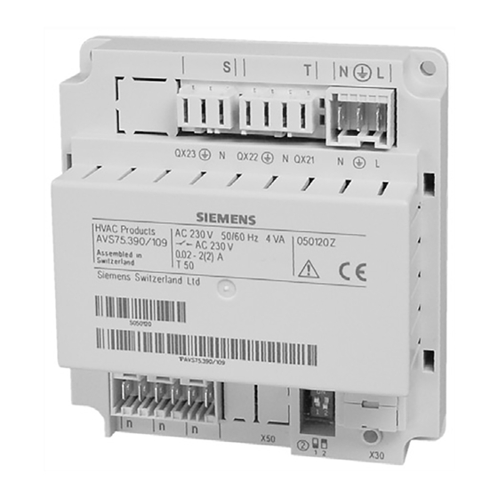
B 2 B 2 Q 3 B 2
2 0
0 2 1 0 . 5 V o l t
B 2 B 3 Q 3
U h r z e i t u n d D a t u m B e d i e n e i n h e i t
F u n k
S o m m e r z
S o m m e r z
J a h r
T a g / M o
Z e i t p r o g r a m m H e i z k r e i s 1 Z e i t p r o g r a m m H e i z k r e i s 2 S t u n d e n
T W W R T W
S t u n d e n
T k o l T S
T a g / M o
B 2 B 3 Q 3
J a h r
Q 3 Q 3
F a c h m a n
O N
I n b e t r i e b s e t z u n g E n d b e n u t z e r E n d b e n u t z e r I n b e t r i e b s e t z u n g
° C T R
S t u n d e n
0
T a g / M o
F u n k
J a h r U h r z e i t u n d D a t u m B e d i e n e i n h e i t F u n k
5 0 4 5 4 0 3 5 5 5 [ T V w ]
F a c h m a n
T
1 7
1 ° C T
T
B 2 B 3 Q 3
° C
B 2 B 3 Q 3 B 2 B 3 Q 3
1 6 1 8 1 9 2 0
B 2 B 3 Q 3 B 2 B 3 Q 3
T V m a x a k t T V
B 6 Q 5
T R T R K
U h r z e i t u n d D a t u m B e d i e n e i n h e i t
W N
p
n
w
/ M i n u t e n
n a t
n a t
n
/ M i n u t e n
e i t e n d e
e i t b e g i n n
n a t
/ M i n u t e n
RVS13...
RVS53...
AVS75...
AVS37...
QAA75...
QAA78...
QAA55...
Building Technologies

Advertisement

Table of Contents
loading

Summary of Contents for Siemens Albatros 2 RVS13 Series

  • Page 1 U h r z e i t u n d D a t u m B e d i e n e i n h e i t F u n k Z e i t p r o g r a m m H e i z k r e i s 1 Z e i t p r o g r a m m H e i z k r e i s 2 S t u n d e n T a g / M o J a h r S o m m e r z...
  • Page 2 2/109 Siemens User Manual CE1U2357en Building Technologies 2014-07-30...
  • Page 3: Table Of Contents

    Radio link ....................... 22 3.7.2 Room unit QAA78.610 ................... 23 Planning ......................23 Mounting with base ..................23 Mounting without base .................. 24 Connection / power supply ................24 Radio link ....................... 24 3/109 Siemens User Manual CE1U2357en Building Technologies Contents 2014-07-30...
  • Page 4 The settings in detail ..................52 Time of day and date ..................52 Operator section .................... 52 Operation and display ..................52 Heating circuit assignment ................53 Room sensor ....................54 Device data ....................54 4/109 Siemens User Manual CE1U2357en Building Technologies Contents 2014-07-30...
  • Page 5 QX ....................73 Input sensor BX1,2 ..................75 input H1 / H2 ....................75 Types of sensors/readjustments ..............78 Building and room model ................79 Frost protection plant ..................79 5/109 Siemens User Manual CE1U2357en Building Technologies Contents 2014-07-30...
  • Page 6 Operator / room units AVS37.., QAA7x, QAA55 ..........98 Power supply AVS16.290 ................100 Radio module AVS71.390 ................101 Wireless outside sensor AVS13.399 ............102 Radio repeater AVS14.390 ................103 sensor characteristics .................. 104 6/109 Siemens User Manual CE1U2357en Building Technologies Contents 2014-07-30...
  • Page 7 8.8.1 NTC 1 k ....................... 104 8.8.2 NTC 10 k ..................... 105 8.8.3 PT1000 ......................105 7/109 Siemens User Manual CE1U2357en Building Technologies Contents 2014-07-30...
  • Page 8: Summary

    The following products are described in separate pieces of documentation: QAC34 Outside temperature sensor NTC 1 kΩ QAD36 Strap-on temperature sensor NTC 10 kΩ QAZ36 Immersion temperature sensor NTC 10 kΩ 8/109 Siemens User Manual CE1U2357en Building Technologies 1 Summary 2014-07-30...
  • Page 9: Type Summary

    Operation with operator unit (optionally together with room unit) wireless Wire-bound Basic unit RVS… Power section AVS16… Room unit QAA55… / QAA75… / QAA78… Outside sensor AVS13… Operator unit AVS37… Radio module AVS71… 9/109 Siemens User Manual CE1U2357en Building Technologies 1 Summary 2014-07-30...
  • Page 10: Safety Notes

    · When using the products, all requirements specified in chapters "Handling" and "Technical data" must be satisfied · Local regulations (for installation, etc.) must be complied with · Do not open the units. If not observed, warranty by Siemens becomes void 10/109 Siemens...
  • Page 11: Mounting And Installation

    · Housing for wall mounting Mounting method Screwed On DIN rail 2359Z11 A: Mounting B: Removal Note: To mount the controller on a DIN rail, a mounting clip is required! 11/109 Siemens User Manual CE1U2357en Building Technologies 3 Mounting and installation 2014-07-30...
  • Page 12: Dimensions And Drilling Plan

    Total height required Dimension X: For connectors with tongues: Minimum 70 mm For connectors without tongues: Minimum 60 mm 3.2.1 Connection terminals of RVS13.123 050111A RVS13.123/109 000020 S050111000020 1PRVS13.123/109 12/109 Siemens User Manual CE1U2357en Building Technologies 3 Mounting and installation 2014-07-30...
  • Page 13: Connection Terminals Of Rvs13.143

    3.2.2 Connection terminals of RVS13.143 050110A RVS13.143/109 000020 S050110000020 1PRVS13.143/109 3.2.3 Connection terminals of RVS53.183 050113A RVS53.183/109 000020 S050113000020 1PRVS53.183/109 13/109 Siemens User Manual CE1U2357en Building Technologies 3 Mounting and installation 2014-07-30...
  • Page 14: Terminal Markings

    Operator unit / boiler control panel BSB data AGP4S.02A/109 BSB ground Room unit 2 data AGP4S.02A/109 Room unit 2 ground Room unit 1 data AGP4S.02A/109 Room unit 1 ground AGP4S.03D/109 14/109 Siemens User Manual CE1U2357en Building Technologies 3 Mounting and installation 2014-07-30...
  • Page 15 Flow temperature sensor HC1 AGP4S.02G/109 Ground Multifunctional sensor input 1 AGP4S.02F/109 Ground Multifunctional sensor input 2 AGP4S.02F/109 Ground Flow temperature sensor HC2 AGP4S.02G/109 Ground Digital input AGP4S.02F/109 Ground 15/109 Siemens User Manual CE1U2357en Building Technologies 3 Mounting and installation 2014-07-30...
  • Page 16: Extension Module Avs75.390

    X50 of the basic unit using the AVS83.490/109 connecting cable. The connectors are coded. 3.3.1 Connection terminals of AVS75.390 050110A AVS75.390/109 000020 S050110000020 1PAVS75.390/109 = Mixing heating circuit2 16/109 Siemens User Manual CE1U2357en Building Technologies 3 Mounting and installation 2014-07-30...
  • Page 17: Terminal Markings

    Protective earth QX23 Heating circuit pump Low-voltage Terminal Type of connector Operator unit / boiler control panel AVS82.491/109 BX21 Flow temperature sensor HC2 AGP4S.02F/109 Ground Digital input AGP4S.02F/109 Ground 17/109 Siemens User Manual CE1U2357en Building Technologies 3 Mounting and installation 2014-07-30...
  • Page 18: Operator Unit Avs37.294

    The AVS37.294 operator unit must be connected to terminal X30 of the basic unit using the AVS82.491/109 connecting cable. The connectors are coded. Dimensions 42.4 Panel cutout (144) 0.5...3.0 18/109 Siemens User Manual CE1U2357en Building Technologies 3 Mounting and installation 2014-07-30...
  • Page 19: Room Unit Qaa55.110

    When the unit is removed from its base, power is disconnected so that the unit is out of operation. installation · The controller may not be exposed to dripping water Connections BSB data BSB ground Dimensions and drilling plan 19/109 Siemens User Manual CE1U2357en Building Technologies 3 Mounting and installation 2014-07-30...
  • Page 20: Room Unit Qaa75.61X

    When the unit is removed from its base, power is disconnected so that the unit is out of operation. Mounting method Connections Terminal Marking QAA75.610 QAA75.611 BSB data BSB data BSB ground BSB ground Reserved Power supply DC 12 V 20/109 Siemens User Manual CE1U2357en Building Technologies 3 Mounting and installation 2014-07-30...
  • Page 21: Dimensions And Drilling Plan

    Dimensions and drilling plan 2359Z12 21/109 Siemens User Manual CE1U2357en Building Technologies 3 Mounting and installation 2014-07-30...
  • Page 22: Wireless Components

    Prior to connecting the module, the basic unit must be disconnected from power! Dimensions and drilling plan Radio link Establishment of the radio link is described in the following sections which cover the different radio-controlled units. 22/109 Siemens User Manual CE1U2357en Building Technologies 3 Mounting and installation 2014-07-30...
  • Page 23: Room Unit Qaa78.610

    (about 1.5 meters above the floor) · In the case of wall mounting, there must be sufficient clearance above the unit, enabling it to be fitted and removed Mounting with base 23/109 Siemens User Manual CE1U2357en Building Technologies 3 Mounting and installation 2014-07-30...
  • Page 24: Mounting Without Base

    Operator section have been received. The test will be ended Testmode after 24 telegrams. The test will be considered successful when at least 50 % of the telegrams 24/109 Siemens User Manual CE1U2357en Building Technologies 3 Mounting and installation 2014-07-30...
  • Page 25: Dimensions And Drilling Plan

    If the test was not successful, some other mounting location should be chosen or the AVS14.390 radio repeater should be used. Dimensions and drilling plan 2359Z12 25/109 Siemens User Manual CE1U2357en Building Technologies 3 Mounting and installation 2014-07-30...
  • Page 26: Wireless Outside Sensor Avs13.399

    Prerequisite for the radio link is that all components receive power, which means that the radio module must be correctly connected to the basic unit and the batteries must be correctly installed in the room unit. 26/109 Siemens User Manual CE1U2357en Building Technologies...
  • Page 27: Dimensions And Drilling Plan

    3. After the test, press the button on the transmitter of the wireless outside sensor again briefly until the LED extinguishes. Dimensions and drilling plan 79,8 49,7 Ø 14,1 24,5 49,5 27/109 Siemens User Manual CE1U2357en Building Technologies 3 Mounting and installation 2014-07-30...
  • Page 28: Radio Repeater Avs14.390

    2. When radio communication works, the LED on the radio module flashes briefly at 10-second intervals. 3. After the test, press the button on the radio repeater again briefly until the LED extinguishes. Dimensions and drilling plan 28/109 Siemens User Manual CE1U2357en Building Technologies 3 Mounting and installation 2014-07-30...
  • Page 29: Checking The Wireless Components

    Connection to basic unit Terminal Marking Leiterfarben Phase AC 230 V basic unit Brown Protective earth Geen + yellow Neutral conductor Blue Phase AC 230 V burner Black Input burner fault 29/109 Siemens User Manual CE1U2357en Building Technologies 3 Mounting and installation 2014-07-30...
  • Page 30 Mains supply to RVS… basic unit L1 S3 1 2 3 4 5 Fuse 6.3AT Mains switch with green glow lamp Safety limit thermostat 110°C Signal lamp (SLT tripped) Dimensions 30/109 Siemens User Manual CE1U2357en Building Technologies 3 Mounting and installation 2014-07-30...
  • Page 31 (96) 0.5...3.0 +0.8 31/109 Siemens User Manual CE1U2357en Building Technologies 3 Mounting and installation 2014-07-30...
  • Page 32: Commissioning

    For detailed diagnostics of the plant, check operating pages “Diagnostics heat source“ and “Diagnostics consumer”. 4.1 Basic units Checking the LED LED off: No power supply LED on: Ready to operate LED flashes Local faults 32/109 Siemens User Manual CE1U2357en Building Technologies 4 Commissioning 2014-07-30...
  • Page 33: Handling

    Selecting the heating mode Operator unit Displaying information Confirmation of setting Chimney sweep function STB test Manual control Quitting the setting Adjustment of room Comfort Service connector (BSB) setpoint Navigation and settings 33/109 Siemens User Manual CE1U2357en Building Technologies 5 Handling 2014-07-30...
  • Page 34: Display Choices

    During continuous operation with reduced setpoint: Active Protective mode When using Protection, the heating system is off. But it remains protected against frost (frost protection temperature), provided there is no power failure. Characteristics of Protection: 34/109 Siemens User Manual CE1U2357en Building Technologies 5 Handling 2014-07-30...
  • Page 35: Selecting Dhw Heating

    · The occupancy button is only active in automatic operation · The current selection is active until the next switching action according to the heating program occurs Displaying information The Info button is used to display information. 35/109 Siemens User Manual CE1U2357en Building Technologies 5 Handling 2014-07-30...
  • Page 36 (enduser / commissioning / heating engineer). Reset ? After activation with the OK button, the display shows a flashing “Yes“. 36/109 Siemens User Manual CE1U2357en Building Technologies 5 Handling...
  • Page 37 If released, the test will be aborted. The SLT test is shown on the display. The test must be made by qualified staff since the boiler temperature will be raised above the maximum limitations. 37/109 Siemens User Manual CE1U2357en Building Technologies...
  • Page 38: Programming

    The display shows the hours flashing. AUTO Turn the setting knob until the hours of the time of day are correct. Time of day and date To confirm, press the OK button. Hours / minutes 38/109 Siemens User Manual CE1U2357en Building Technologies 5 Handling 2014-07-30...
  • Page 39: User Levels

    Text3 Operator section You are given a choice of user AUTO levels. Turn the setting knob until the required user level is reached. Enduser Text3 Commissioning Press the OK button. 39/109 Siemens User Manual CE1U2357en Building Technologies 5 Handling 2014-07-30...
  • Page 40: Setting Structure For "Enduser

    1...24 h Start of summer time Time program heating circuit 2 End of summer time Minutes 0...60 min Time program heating circuit P Holidays heating circuit 1 Diagnostics of consumers 40/109 Siemens User Manual CE1U2357en Building Technologies 5 Handling 2014-07-30...
  • Page 41: Overview Of Settings

    Missing ¦ Ready ¦ No reception ¦ Change batt Repeater Missing ¦ Ready ¦ No reception Operator unit Missing ¦ Ready ¦ No reception ¦ Change batt Service unit Missing ¦ Ready ¦ No reception ¦ Change batt 41/109 Siemens User Manual CE1U2357en Building Technologies 5 Handling 2014-07-30...
  • Page 42 2nd phase off 24:00 00:00 24:00 hh:mm 3rd phase on 24:00 00:00 24:00 hh:mm 3rd phase off 24:00 00:00 24:00 hh:mm Default values No ¦ Yes Holidays heating circuit 1 42/109 Siemens User Manual CE1U2357en Building Technologies 5 Handling 2014-07-30...
  • Page 43 Floor curing function Off ¦ Functional heating ¦ Curing heating ¦ Functional/curing heating¦ Manually Floor curing setp manually °C Recooling storage tank Always Off ¦ Heating mode ¦ Always 43/109 Siemens User Manual CE1U2357en Building Technologies 5 Handling 2014-07-30...
  • Page 44 Heating curve slope 1.50 0.10 4.00 1321 F Heating curve displacement -4.5 °C 1326 F Heating curve adaption ¦ On - - - / 8 1330 E Summer/winter heating limit °C 44/109 Siemens User Manual CE1U2357en Building Technologies 5 Handling 2014-07-30...
  • Page 45 ¦ On 1663 F Circulaton setpoint °C boiler 2210 F Setpoint min ZN 2211 OEM Setpoint manual °C control 2212 F Setpoint max Setpoint manual ZN 2213 OEM °C control 45/109 Siemens User Manual CE1U2357en Building Technologies 5 Handling 2014-07-30...
  • Page 46 None ¦ DHW sensor B31 ¦ Collector sensor B6 ¦ Return sensor B7 5931 I Sensor input BX2 None None ¦ DHW sensor B31 ¦ Collector sensor B6 ¦ Return sensor B7 46/109 Siemens User Manual CE1U2357en Building Technologies 5 Handling 2014-07-30...
  • Page 47 History 1 Error code 1 6802 F History 2 Error code 1 6804 F History 3 Error code 1 6806 F History 4 Error code 1 6808 F History 5 47/109 Siemens User Manual CE1U2357en Building Technologies 5 Handling 2014-07-30...
  • Page 48 7881 I 1st burner stage E1 0V ¦ 230V State of plant 8000 I State heating circuit 1 8001 I State heating circuit 2 8002 I State heating circuit P 48/109 Siemens User Manual CE1U2357en Building Technologies 5 Handling 2014-07-30...
  • Page 49 ¦ On 8830 I DHW temp 1 140.0 °C 8831 I DHW temp setpoint 80.0 °C 8832 I DHW temp 2 140.0 °C 8835 I DHW circulation temp 140.0 °C 49/109 Siemens User Manual CE1U2357en Building Technologies 5 Handling 2014-07-30...
  • Page 50 130.0 °C 9001 I Flow temp setpoint H2 130.0 °C 9005 I Water pressure H1 10.0 9031 I Relay output QX1 ¦ On 9032 I Relay output QX2 ¦ On 50/109 Siemens User Manual CE1U2357en Building Technologies 5 Handling 2014-07-30...
  • Page 51: Qaa55

    (timeout). P1 = 2 Storage with confirmation: A setpoint readjustment with the knob is adopted only after pressing the operating mode button. 51/109 Siemens User Manual CE1U2357en Building Technologies 5 Handling 2014-07-30...
  • Page 52: The Settings In Detail

    Within the programming level, the programming lock can temporarily be overridden. To do this, press the OK and ESC buttons simultaneously for 3 seconds. Temporary deactivation of the programming lock is maintained until programming is quit 52/109 Siemens User Manual CE1U2357en Building Technologies...
  • Page 53: Heating Circuit Assignment

    Independently The action of operation is queried on the display as soon as the operating mode button is pressed or the setting knob is operated. Operation HCP 53/109 Siemens User Manual CE1U2357en Building Technologies 6 The settings in detail 2014-07-30...
  • Page 54: Room Sensor

    Same as on operating line 130 Repeater Same as on operating line 130 Operator unit Same as on operating line 130 Service unit Same as on operating line 130 Delete all devices 54/109 Siemens User Manual CE1U2357en Building Technologies 6 The settings in detail 2014-07-30...
  • Page 55: Time Programs

    The holiday program is used to switch the heating circuits to a selectable operating level according to calendar dates. · The holiday program can only be used in “Automatic“ operation 55/109 Siemens User Manual CE1U2357en Building Technologies 6 The settings in detail...
  • Page 56: Heating Circuits

    The ranges of adjustable setpoints result from the interdependencies, as this is shown in the following graph. 56/109 Siemens User Manual CE1U2357en Building Technologies 6 The settings in detail...
  • Page 57: Heating Curve

    There should be no thermostatic radiator valves in the reference room (mounting location of the room sensor) (If such valves are installed, they must be set to their fully open position) 57/109 Siemens User Manual CE1U2357en Building Technologies 6 The settings in detail...
  • Page 58: Eco Functions

    E.g. Comfort setpoint (TRw) 22°C 24-hour heating limit (THG) -3°C Changeover temperature (TRw-THG) heating off = 19°C Switching differential (fixed) -1°C Changeover temperature heating on = 18°C 58/109 Siemens User Manual CE1U2357en Building Technologies 6 The settings in detail 2014-07-30...
  • Page 59: Flow Temperature Setpoint Limitations

    This type of compensation calls for a correct adjustment of the heating curve since in that case the control gives no consideration to the room temperature. 59/109 Siemens User Manual CE1U2357en Building Technologies 6 The settings in detail...
  • Page 60: Room Temp Limitation

    Room temperature limitation does not work in the case of pure weather compensation. °C TRw+SDR Actual value room temp Room temperature setpoint Room’s switching differential Pump Time of day Boost heating Line no. Operating line 1070 1370 Boost heating 60/109 Siemens User Manual CE1U2357en Building Technologies 6 The settings in detail 2014-07-30...
  • Page 61: Quick Setback

    76.6 10 °C 13.4 33.5 5 °C 21.5 0 °C 15.8 -5 °C 12.5 -10 °C 10.3 -15 °C -20 °C Duration of quick setback in hours 61/109 Siemens User Manual CE1U2357en Building Technologies 6 The settings in detail 2014-07-30...
  • Page 62 · Quick setback is possible with or without room sensor 62/109 Siemens User Manual CE1U2357en Building Technologies 6 The settings in detail 2014-07-30...
  • Page 63: Optimum Start / Stop Control

    Comfort setpoint. TRwA1 TRwA2 TAgem TRwA1 Red setpoint increase start TRwA2 Red setpoint increase end 63/109 Siemens User Manual CE1U2357en Building Technologies 6 The settings in detail 2014-07-30...
  • Page 64: Overtemp Prot Pump Heating Circuit

    Functional heating (Fh) Curing heating (Bh) Functional/curing heating Curing heating/ functional heating Manually 1151 1451 Floor curing setp manually 1455 Floor curing setp current 1456 Floor curing day current 64/109 Siemens User Manual CE1U2357en Building Technologies 6 The settings in detail 2014-07-30...
  • Page 65: Recooling

    The surplus heat stored in the heat exchanger can be drawn off by space heating. This can be adjusted separately for each heating circuit. (Also refer to operating page “DHW storage tank“, operating line “Recoolign boiler/HC“) 65/109 Siemens User Manual CE1U2357en Building Technologies...
  • Page 66: Domestic Hot Water

    DHW setpoint. This way, the DHW is heated independently of the heating circuits. Example: Priority Line no. Operating line 1630 Charging priority Absolute Shifting None MC shifting, PC absolute 66/109 Siemens User Manual CE1U2357en Building Technologies 6 The settings in detail 2014-07-30...
  • Page 67: Legionella Function

    During the time the legionella function is performed, there is a risk of scalding when opening the taps. circulating pump Line no. Operating line 1660 Circulating pump release Time program 3 / HCP 67/109 Siemens User Manual CE1U2357en Building Technologies 6 The settings in detail 2014-07-30...
  • Page 68: Boiler

    Maintained boiler return temperature makes it possible to impact the consumers via the following settings: · “Return influence consumers“, using operating line line 2272 · “Control bypass pump“, using operating line 2291 68/109 Siemens User Manual CE1U2357en Building Technologies 6 The settings in detail...
  • Page 69: Solar

    When the collector temperature returns to a level of 1 °K above the frost protection temperature, the collector pump will be deactivated again: TKol > TKolFrost + 1 Overtemperature protection for the collector Line no. Operating line 69/109 Siemens User Manual CE1U2357en Building Technologies 6 The settings in detail 2014-07-30...
  • Page 70 Storage tank safety temperature Storage tank temperature TKolUe Collector temperature for overtemperature protection TSpmax Maximum charging temperature Tkol Collector temp On / Off Collector pump Temperature Time of day 70/109 Siemens User Manual CE1U2357en Building Technologies 6 The settings in detail 2014-07-30...
  • Page 71: Evaporation Temperature Of Medium

    · If the collector is cold, the energy can be emitted to the environment via the Recooling collector collector’s surfaces Electric immersion heater Line no. Operating line 5060 El imm heater optg mode Substitute 71/109 Siemens User Manual CE1U2357en Building Technologies 6 The settings in detail 2014-07-30...
  • Page 72 For the electric immersion heater, time program 4/DHW of the local controller is used. Example: El immersion heater External control thermostat control The storage tank is charged with an external control thermostat without setpoint compensation of the controller. DHW sensor 72/109 Siemens User Manual CE1U2357en Building Technologies 6 The settings in detail 2014-07-30...
  • Page 73: Configuration

    Q2 becomes a boiler pump, provided the boiler pump is not yet defined for use at a multifunctional relay output QX... output relay QX Line no. Operating line 5890 Relay output QX1 73/109 Siemens User Manual CE1U2357en Building Technologies 6 The settings in detail 2014-07-30...
  • Page 74 The connected pump is used for circulating the boiler water. Bypass pump Q12 The connected pump serves as a boiler bypass pump for maintaining the boiler return temperature. Alarm output K10 74/109 Siemens User Manual CE1U2357en Building Technologies 6 The settings in detail 2014-07-30...
  • Page 75: Input Sensor Bx1,2

    Optg mode changeover HC1 Optg mode changeover HC2 Optg mode changeover HCP Heat generation lock Error/alarm message minimum flow temperature setpoint Heat request pressure measurement 5951 contact type input H1 75/109 Siemens User Manual CE1U2357en Building Technologies 6 The settings in detail 2014-07-30...
  • Page 76 Heat request Heat generation receives heat requests in the form of voltage signals (DC 0...10 V). The associated setpoint is to be adjusted on operating line 5954. 76/109 Siemens User Manual CE1U2357en Building Technologies 6 The settings in detail...
  • Page 77 The flow temperature setpoint corresponding to the voltage level of 10 V can be adjusted with parameter “Heat request 10V H1/H2“. 77/109 Siemens User Manual CE1U2357en Building Technologies 6 The settings in detail...
  • Page 78: Types Of Sensors/Readjustments

    Readjustm collector The temperature display can be readjusted. sensor Readjustm outside sensor The measured value of the outside temperature can be readjusted by +/- 3 K. 78/109 Siemens User Manual CE1U2357en Building Technologies 6 The settings in detail 2014-07-30...
  • Page 79: Building And Room Model

    Time of day and date, operator section, radio communication, and all time programs. Plant diagrams Line no. Operating line 6212 Check no. heat source 1 6215 Check no. storage tank 6217 Check no. heating circuits 79/109 Siemens User Manual CE1U2357en Building Technologies 6 The settings in detail 2014-07-30...
  • Page 80: Device Data

    The check numbers are always arranged from the right. Preceding 0s are not shown. Device data Line no. Operating line 6220 Software version The software version indicated here represents the current version of the basic unit. 6.9 Faults 80/109 Siemens User Manual CE1U2357en Building Technologies 6 The settings in detail 2014-07-30...
  • Page 81: Maintenance / Service

    The function is deactivated by setting -.- on this operating line, or automatically after a timeout of 1 hour. 81/109 Siemens User Manual CE1U2357en Building Technologies 6 The settings in detail...
  • Page 82: Manual Control

    Line no. Operating line 7170 Telephone customer service Setting of phone number that appears on the info display. 6.11 Input / output test Line no. Operating line 7700…7881 82/109 Siemens User Manual CE1U2357en Building Technologies 6 The settings in detail 2014-07-30...
  • Page 83: State Of Plant

    Heating mode Comfort optimum stop control Heating mode Reduced Heating mode Reduced Frost protection room active Frost protection flow active Frost protection plant active Frost protection active 83/109 Siemens User Manual CE1U2357en Building Technologies 6 The settings in detail 2014-07-30...
  • Page 84 Protective startup, low-fire Return temperature limitation, high-fire Return temperature limitation, low-fire Released, high-fire Released, low-fire Overrun active In operation Released Released Frost protection plant active Frost protection active 84/109 Siemens User Manual CE1U2357en Building Technologies 6 The settings in detail 2014-07-30...
  • Page 85: Diagnostics Heat Source

    Radiation insufficient 6.13 Diagnostics heat source For making diagnostics, the various setpoints, actual values, relay switching states and meter readings can be displayed. Line no. Operating line 8610…8699 85/109 Siemens User Manual CE1U2357en Building Technologies 6 The settings in detail 2014-07-30...
  • Page 86: Diagnostics Consumers

    6.14 Diagnostics consumers For making diagnostics, the various setpoints, actual values, relay switching states and meter readings can be displayed. Line no. Operating line 8700…9099 86/109 Siemens User Manual CE1U2357en Building Technologies 6 The settings in detail 2014-07-30...
  • Page 87: List Of Displays

    Water pressure heating circuit too low (pressure dropped below lower limit 1) Replace battery of outside sensor Water pressure 2 heating circuit too low (pressure dropped below lower limit 2) 87/109 Siemens User Manual CE1U2357en Building Technologies 6 The settings in detail 2014-07-30...
  • Page 88: Plant Diagrams

    The basic diagrams show possible applications that can be implemented without using the multifunctional outputs. 7.1 Basic diagram RVS13.123 Standard diagram DHW heating with diverting valve 7.1.1 Basic diagram RVS13.12x with AVS75.390 Standard diagram 88/109 Siemens User Manual CE1U2357en Building Technologies 7 Plant diagrams 2014-07-30...
  • Page 89: Basic Diagram Rvs13.143

    7.2 Basic diagram RVS13.143 Standard diagram DHW heating with diverting valve 7.2.1 Basic diagram RVS13.14x with AVS75.390 Standard diagram 89/109 Siemens User Manual CE1U2357en Building Technologies 7 Plant diagrams 2014-07-30...
  • Page 90: Basic Diagram Rvs53.183

    The type and number of auxiliary functions that can be applied depend on the multifunctional outputs and inputs QX… or BX… Circulating pump Electric immersion heater 90/109 Siemens User Manual CE1U2357en Building Technologies 7 Plant diagrams 2014-07-30...
  • Page 91: Collector Pump And Collector Sensor

    Collector pump and collector sensor Pump H1/2 Q15/18 Boiler pump 91/109 Siemens User Manual CE1U2357en Building Technologies 7 Plant diagrams 2014-07-30...
  • Page 92: Bypass Pump

    Bypass pump Heating circuit pump HCP 2. DHW sensor 92/109 Siemens User Manual CE1U2357en Building Technologies 7 Plant diagrams 2014-07-30...
  • Page 93: Return Sensor

    Pump H1/2 QX1, QX2 heating circuit pump HCP QX1, QX2 1. eating circuit mixing valve Y1, Y2 2. eating circuit mixing valve Y5, Y6 electric immersion heater QX1, QX2 93/109 Siemens User Manual CE1U2357en Building Technologies 7 Plant diagrams 2014-07-30...
  • Page 94 DHW sensor top 2. DHW sensor bottom BX1, BX2 Collector sensor BX1, BX2 Return sensor BX1, BX2 Outside sensor Room unit 1 CL-, CL+ Room unit 2 CL-, CL+ 94/109 Siemens User Manual CE1U2357en Building Technologies 7 Plant diagrams 2014-07-30...
  • Page 95: Technical Data

    Max. switch-on current Max. total current (of all relays) AC 6 A Rated voltage range AC (24...230) V (for potentialfree outputs) External supply line protection Refer to section "Power supply" 95/109 Siemens User Manual CE1U2357en Building Technologies 8 Technical data 2014-07-30...
  • Page 96 Transport to EN 60721-3-2 class 2K3, temperature -25…70 °C Operation to EN 60721-3-3 class 3K5, temperature 0...50 °C (noncondensing) Weight Weight (excl. packaging) RVS13.123: 566 g RVS13.143: 566 g RVS53.183: 776 g 96/109 Siemens User Manual CE1U2357en Building Technologies 8 Technical data 2014-07-30...
  • Page 97: Extension Module Avs75.390

    2-wire connection, not interchangeable Interfaces Max. cable length Basic unit – peripheral device 200 m Max. total length 400 m (max. cable capacitance) 60 nF) Min. cross-sectional area 0.5 mm 97/109 Siemens User Manual CE1U2357en Building Technologies 8 Technical data 2014-07-30...
  • Page 98: Operator / Room Units Avs37

    EN 60730-1 Protection degree of housing IP20 for QAA7../ QAA55.. IP40 for AVS37.. (when mounted) according to EN 60529 Degree of pollution 2 according to EN 60730-1 98/109 Siemens User Manual CE1U2357en Building Technologies 8 Technical data 2014-07-30...
  • Page 99 2K3, temperature -20...70 °C Operation to EN 60721-3-3 class 3K5, temperature 0...50 °C (noncondensing) Weight Weight (excl. packaging) AVS37.294: 160 g QAA75.61x: 170 g QAA78.610: 312 g QAA55.110: 115 g 99/109 Siemens User Manual CE1U2357en Building Technologies 8 Technical data 2014-07-30...
  • Page 100: Power Supply Avs16.290

    1K3, temperature -20…65°C Transport to EN 60721-3-2 class 2K3, temperature -25…70 °C Operation to EN 60721-3-3 class 3K5, temperature 0...50 °C (noncondensing) Weight Weight (excl. packaging) 310 g 100/109 Siemens User Manual CE1U2357en Building Technologies 8 Technical data 2014-07-30...
  • Page 101: Radio Module Avs71.390

    1K3, temperature -20…65°C Transport to EN 60721-3-2 class 2K3, temperature -25…70 °C Operation to EN 60721-3-3 class 3K5, temperature 0...50 °C (noncondensing) Weight Weight (excl. packaging) 54 g 101/109 Siemens User Manual CE1U2357en Building Technologies 8 Technical data 2014-07-30...
  • Page 102: Wireless Outside Sensor Avs13.399

    Outside temperature Outside sensor acquisition -50...50 °C Measuring range max. 5 m Cable length Weight (excl. packaging) radio transmitter: 160 g Weight outside sensor QAC34: 73 g 70 g cable 102/109 Siemens User Manual CE1U2357en Building Technologies 8 Technical data 2014-07-30...
  • Page 103: Radio Repeater Avs14.390

    Transport to EN 60721-3-2 class 2K3, temperature -25…70 °C Operation to EN 60721-3-3 class 3K5, temperature 0...50 °C (noncondensing) Weight (excl. packaging) radio repeater 112 g Weight power supply 195 g 103/109 Siemens User Manual CE1U2357en Building Technologies 8 Technical data 2014-07-30...
  • Page 104: Sensor Characteristics

    50.0 -8.0 4'152 22.0 1'125 -7.0 3'958 23.0 1'081 -6.0 3'774 24.0 1'040 -5.0 3'600 25.0 1'000 -4.0 3'435 26.0 -3.0 3'279 27.0 -2.0 3'131 28.0 -1.0 2'990 29.0 104/109 Siemens User Manual CE1U2357en Building Technologies 8 Technical data 2014-07-30...
  • Page 105 1000.0 1309.0 1610.5 1019.5 1328.0 1629.1 1039.0 1347.1 1647.7 1058.5 1366.1 1666.3 1077.9 1385.1 1684.8 1097.3 1404.0 1703.3 1116.7 1422.9 1721.7 1136.1 1441.8 1740.2 1155.4 1460.7 1758.6 1174.7 1479.5 105/109 Siemens User Manual CE1U2357en Building Technologies 8 Technical data 2014-07-30...
  • Page 106 ............64 increase of Reduced setpoint ........63 input / output test ............82 date ................52 input test sensor ............83 default settings ............55 default values ............55 language ..............52 106/109 Siemens User Manual CE1U2357en Building Technologies 8 Technical data 2014-07-30...
  • Page 107 ............71 quick setback ............61 types of compensation ..........59 radio weather compensation with room influence ....59 binding ..............54 weekday ..............52 test mode ............. 54 wireless ..............54 107/109 Siemens User Manual CE1U2357en Building Technologies 2014-07-30...
  • Page 108 108/109 Siemens Benutzerhandbuch CE1U2357de Building Technologies 8 Technical data 2014-07-30...
  • Page 109 ID: 40111 ID: 40112 (PDF) Siemens Schweiz AG © 2005-2014 Siemens Building Technologies AG Siemens Switzerland Ltd Subject to alteration Building Technologies Group Gubelstrasse 22 CH -6301 Zug Tel. +41 41-724 24 24 Fax +41 41-724 35 22 www.sbt.siemens.com 109/109...

Table of Contents