
Related Manuals for Siemens Raja+ 3TE7431-2BC24-1A Series


Summary of Contents for Siemens Raja+ 3TE7431-2BC24-1A Series
- Page 1 Installation, Maintenance & Troubleshooting Guide For RAJA Agriculture Starters & Controllers...
-
Page 2: Table Of Contents
Contents: 5. Fully Automatic Star Delta Controller with WLC: 5.1 Product description 5.2 Wiring diagram 5.3 Technical Details 5.4 Installation 5.5 Operating procedure in normal condition 5.6 Troubleshooting guidelines in case any incoming fault is present before switching ON the motor 5.7 Troubleshooting guidelines in fault condition when motor stops while it is in running condition 5.8 Troubleshooting guidelines in case any fault is at the load side... -
Page 3: Fully Automatic Star Delta Controller With Wlc
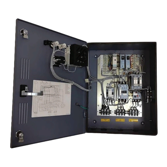
Installation, Maintenance & Troubleshooting guide | Version 05 Fully Automatic Star Delta Controller with WLC 5.1: Product description Fig:12 FASD Controller 1. ‘ON’ push button (green) 2. ‘OFF/RESET’ push button (red) 3. Door knob 4. Metal Enclosure 5. Door 6. Mechanical Latch (OFF push button) to be used for preventing undesired ON operation of Controller 7. - Page 4 Installation, Maintenance & Troubleshooting guide | Version 05 Inside view of Fully Automatic Star Delta Controller with WLC 1: Amber LED 8: WLC operating modes 2: Green LED 9: Starter Operating Modes 3: Rocker Switch 10: Line monitoring relay 4: AV meter 11: Water Level Controller 5: Phase Selector switch 12: Contactor...
-
Page 5: Wiring Diagram
Installation, Maintenance & Troubleshooting guide | Version 05 5.2: Wiring Diagram: FASD controller with WLC... - Page 6 Installation, Maintenance & Troubleshooting guide | Version 05 5.21 Control logic diagram...
- Page 7 Installation, Maintenance & Troubleshooting guide | Version 05 5.22 Power circuit diagram...
-
Page 8: Technical Details
Installation, Maintenance & Troubleshooting guide | Version 05 5.3: Technical details Table: 25 Technical details-FASD Controller with WLC Max. Nominal Line & Recommended Star Line HRC fuses (HP / Delta Overload Range Cu cable size Type contactor Monitoring rating Contactor Relay (sq:mm) Type... - Page 9 Installation, Maintenance & Troubleshooting guide | Version 05 Diagrammatic representation of the 3x modes of WLCA: Delivery mode Suction mode Dual Tank mode Fig.11 For Delivery mode to become operational: P2, P3 Sensor should be out of water For Suction mode to become operational: P1, P2, P3 Sensor should be inside water For Dual tank mode to become operational: P1,P2, P3 Sensor should be inside water &...
-
Page 10: Installation
Installation, Maintenance & Troubleshooting guide | Version 05 5.4: Installation • Open the door by rotating the door lock anticlockwise. • Mount the starter on a vertical wall/ plate free from vibrations with proper nuts and bolts. Refer operating instruction for mounting dimensions. •... - Page 11 • If the relay trips even when set at rated motor current the suitability of the starter/relay for the particular application should be checked with the nearest Siemens office. Operating Characteristics: The given characteristics (Fig. 6) are average values of all ranges and sizes of bimetal relays and are mainly intended to indicate the inverse time current characteristics &...
- Page 12 Installation, Maintenance & Troubleshooting guide | Version 05 Table: 25B Terminal torque values Sr. No Type Size Torque 3TS30..32 0.8-1.4Nm 3TS33/34 1.0-1.5Nm 3TS35 2.5-3.0Nm Terminal block 30A 0.8-1.4Nm Terminal block 60A 1.5-2.1Nm Contact block 3SB5 M3.5 0.8-1.2Nm Aux terminal (side add on) of 3TS33/34, 3TS35/36 M3.5 0.8-1.4Nm 3TX4010-2A...
-
Page 13: Operating Procedure In Normal Condition
Installation, Maintenance & Troubleshooting guide | Version 05 5.5: Operating procedure in normal condition Table: 26 FASD Controller with WLC operating sequence in normal condition Amber LMR-A WLCA 3 main Rocker LMR-A Amber ‘ON’ Push Starter Green Tank Mode Mode supply switch On-Delay... - Page 14 Installation, Maintenance & Troubleshooting guide | Version 05 Starter operation: LMR-A: Manual mode a. WLCA- Delivery mode 14A : Keep the LMR-A in Manual mode. 14B : Keep the WLC-A in Delivery mode. 14C : Switch ON 3-Phase incoming main supply. 14D : Turn ON the rocker switch (Using the selector switch position in RY,YB, BR the set voltage can be checked which is indicated in AV meter).
- Page 15 Installation, Maintenance & Troubleshooting guide | Version 05 LMR-A: Manual mode c. WLCA- Dual tank mode 14A : Keep the LMR-A in Manual mode. 14B : Keep the WLC-A in Dual tank mode. 14C : Switch ON 3-Phase incoming main supply. 14D : Turn ON rocker switch 14E : Amber LED will start blinking for a period of min 0.5 min.
- Page 16 Installation, Maintenance & Troubleshooting guide | Version 05 LMR-A: Auto mode b. WLCA- Suction mode 14A : Keep the LMR-A in Auto mode. 14B : Keep the WLC-A in suction mode. 14C : Switch ON the 3-Phase incoming main supply. 14D : Turn ON the rocker switch.
- Page 17 Installation, Maintenance & Troubleshooting guide | Version 05 LMR-A: Bypass mode a. WLCA- Delivery mode 14A : Keep the LMR-A in Bypass mode. 14B : Keep the WLC-A in Delivery mode. 14C : Switch ON the 3-Phase incoming main supply. (*Customer may switch ON the starter directly after switching ON the 3 phase incoming supply irresepctive of Blinking status as there is only indication for incoming supply faults and no Protection in Bypass mode).
- Page 18 Installation, Maintenance & Troubleshooting guide | Version 05 LMR-A: Bypass mode c. WLCA- Dual tank mode 14A : Keep the LMR-A in Bypass mode. 14B : Keep the WLC-A in Dual tank mode. 14C : Switch ON 3-Phase incoming main supply. (*Customer may switch ON the starter directly after switching ON the 3 phase incoming supply irresepctive of Blinking status as there is only indication for incoming supply faults and no Protection in Bypass mode).
-
Page 19: Troubleshooting Guidelines In Case Any Incoming Fault Is
Installation, Maintenance & Troubleshooting guide | Version 05 5.6: Troubleshooting Guidelines in case any incoming supply fault is present before switching ON the Starter Table: 27 FASD Controller with WLCA operating sequence in fault condition Possible Corre- ‘ON’ Starter Tank LMR-A WLCA Rocker... - Page 20 Installation, Maintenance & Troubleshooting guide | Version 05 Starter Fault conditon: 1) LMR-A: Manual mode a. WLCA- Delivery mode 15A : Check the mode of LMR-A, if it is manual mode. 15B : Check the mode of WLC-A, if it is Delivery mode. 15C : Switches ON the 3-Phase incoming main supply.
- Page 21 Installation, Maintenance & Troubleshooting guide | Version 05 15J : Amber LED will remain ON continously indicating that the fault is cleared 15K : Press the Green ON push button to switch ON the starter. 15L : Starter gets switched ON. 15M : Green LED turns ON indicating that the starter is ON.
- Page 22 Installation, Maintenance & Troubleshooting guide | Version 05 4) LMR-A: Auto mode a. WLCA- Delivery mode : Check the mode of LMR-A, if it is Auto mode. : Check the mode of WLC-A, if it is Delivery mode. 15C to 15J : Follow steps from 15C to 15J of Manual &...
-
Page 23: Troubleshooting Guidelines In Fault Condition When Motor Stops While It Is In Running Condition
Installation, Maintenance & Troubleshooting guide | Version 05 5.7: Troubleshooting Guidelines in fault condition when motor stops while it is in running condition Table: 29 FASD Controller with WLCA operating sequence in fault condition Motor LMR-A WLCA Amber Possible Corrective Amber ‘ON’... - Page 24 Installation, Maintenance & Troubleshooting guide | Version 05 Starter Fault conditon: 1. LMR-A: Manual mode a. WLCA- Delivery mode : Motor suddenly stops after running for some time. : Check the mode of LMR-A, if it is Manual mode. : Check the mode of WLCA, if it is Delivery mode. : Amber LED will start blinking 16E to 16J : Follow steps from 15H to 15M of LMR-A manual mode &...
- Page 25 Installation, Maintenance & Troubleshooting guide | Version 05 5. LMR-A: Auto mode b. WLCA- Suction mode : Motor suddenly stops after running for some time. : Check the mode of LMR-A, if it is Auto mode. : Check the mode of WLCA, if it is Suction mode. : Amber LED will start blinking 16E to 16G : Follow steps from 15H to 15J of LMR-A Manual mode &...
- Page 26 It helps our customers to thrive, communities to progress and supports sustainable development to protect our planet for the next generation. Creating environments that care. siemens.com/smart-infrastructure Published by Siemens Ltd Smart Infrastructure Electrical Products R&D Building, 48, Thane-Belapur Road Thane 400708, India Article no.
Need help?
Do you have a question about the Raja+ 3TE7431-2BC24-1A Series and is the answer not in the manual?
Questions and answers