Table of Contents
Advertisement
Quick Links
STILLA
ASSEMBLY INSTRUCTIONS
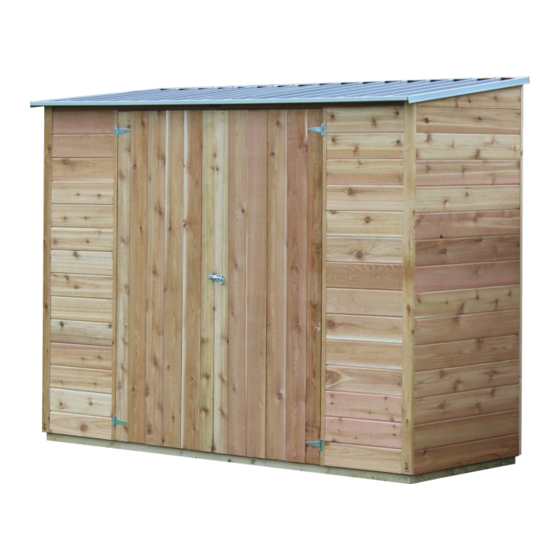
'Acacia' 8x3
S3105
Every part needed to construct your shed is included inside the pack; cedar
panels, doors, windows, hardware kits & roof sheeting. Please ensure you fully
unpack all the parts & check against the parts checklist before contacting
customer service about anything you believe may be missing. Thank-you!
Caution
Advertisement
Table of Contents

Subscribe to Our Youtube Channel
Related Manuals for STILLA Acacia


Summary of Contents for STILLA Acacia
- Page 1 STILLA ASSEMBLY INSTRUCTIONS ‘Acacia’ 8x3 S3105 Every part needed to construct your shed is included inside the pack; cedar panels, doors, windows, hardware kits & roof sheeting. Please ensure you fully unpack all the parts & check against the parts checklist before contacting customer service about anything you believe may be missing.
- Page 2 Please be careful when handling all components, some parts have sharp metal edges. Always wear work gloves, eye protection and long sleeves when assembling or maintaining your shed. Tools required for assembly • Level • Phillips head drive • Drill •...
- Page 3 ACACIA 8x3 PARTS CHECKLIST Part Code Checked Part Description Cedar Clad Panel 1200x1890mm Tapered Panel (Left) 900x1875mm Tapered Panel (Right) 900x1875mm Cedar Clad Front Panel 495x1805mm 8x3 Door 700x1770mm (Full Cedar) 2565mm Channel - ZINC 2565mm L Flashing – ZINC 1040mm L Flashing –...
- Page 4 If no floor option was purchased, go to step 2.0 (Wall Assembly) STEP 1.0 FLOOR KIT 1.0 – FLOOR KIT PART CODE QTY DESCRIPTION End Plate 2470mm Single Joist 830mm Double Joist 830mm (42x35mm part of DJ goes at the top inside) 100BS 100mm Batten screw (Heavy Duty Floor Only) 75mm Nail (Rebated Floor Only)
- Page 5 STEP 1.1 FLOORING INSTALLATION 1.1 – FLOOR INSTALLATION PART CODE QTY DESCRIPTION Floor Board 1798x485mm Floor Board 598x485mm Floor Board 1798x326mm Floor Board 598x326mm 50PS 50mm Phillips screw 1.1 – FLOOR SHEETS Fasten floor sheets to floor frame as shown below using 50PS P a g e...
-
Page 6: Wall Assembly
STEP 2.0 WALL ASSEMBLY 2.0 - ASSEMBLY PARTS – WALL ASSEMBLY PART CODE QTY DESCRIPTION Front panel Tapered panel left 65HHS 65mm hex head screw 2.0 - ASSEMBLY – WALL ASSEMBLY Screw through FP into LP (top, centre & bottom) using 3 x 65HHS. (Holding studs flush on the outside) Note –... - Page 7 STEP 2.1 WALL ASSEMBLY 2.1 - ASSEMBLY PARTS – WALL ASSEMBLY PART CODE QTY DESCRIPTION 1200mm panel 65HHS 65mm hex head screw 2.1 - ASSEMBLY – WALL ASSEMBLY Screw through P into LP (Top, centre & bottom) using 3 x 65HHS, holding studs flush on the outside.
- Page 8 STEP 2.2 WALL ASSEMBLY 2.2 - ASSEMBLY PARTS – WALL ASSEMBLY PART CODE QTY DESCRIPTION 1200mm panel 65HHS 65mm hex head screw 2.2 - ASSEMBLY – WALL ASSEMBLY Screw through P into P (Top, centre & bottom) using 3 x 65HHS, holding studs flush on the inside.
- Page 9 STEP 2.3 WALL ASSEMBLY 2.3 - ASSEMBLY PARTS – WALL ASSEMBLY PART CODE QTY DESCRIPTION Tapered panel right 65HHS 65mm hex head screw 2.3 - ASSEMBLY – WALL ASSEMBLY Screw through P into RP (top, centre & bottom) using 3 x 65HHS holding studs flush on the outside.
- Page 10 STEP 2.5 DOOR STEP INSTALLATION 2.5 - ASSEMBLY PARTS –DOOR INSTALLATION PART CODE DESCRIPTION Door Step 40mm Nail 2.5 - ASSEMBLY –DOOR INSTALLATION Nail through DS into floor frame (if floor option was not chosen fasteners are not supplied) P a g e...
-
Page 11: Roof Assembly
STEP 2.6 FASTENING WALLS TO FLOOR 2.6 - ASSEMBLY PARTS – FASTENING WALLS TO FLOOR PART CODE QTY DESCRIPTION 65HHS 65mm hex head screw 2.6 - ASSEMBLY – FASTENING WALLS TO FLOOR Ensure walls are in correct position and straight. Fasten through wall bottom plate in positions shown below. - Page 12 STEP 3.1 ROOF ASSEMBLY 3.1 - ASSEMBLY PARTS – ROOF ASSEMBLY PART CODE QTY DESCRIPTION 2565mm L flashing 2565mm C channel Self-tapping screw 3.1 - ASSEMBLY – ROOF ASSEMBLY Place L on RS (Roof Sheets) as shown in picture. Screw through top, 1 Rib in from each end and into each join of sheet (4 times all up) using ST x 4.
- Page 13 STEP 3.2 ROOF ASSEMBLY 3.2 - ASSEMBLY PARTS – ROOF ASSEMBLY PART CODE QTY DESCRIPTION 1040mm L flashing Self-tapping screw 3.2 - ASSEMBLY – ROOF ASSEMBLY Place L into position, as shown in picture. Screw through L into L at back and C at front. Screw threw 1040L into roof sheet (RS) in centre.
-
Page 14: Roof Installation
STEP 3.4 ROOF INSTALLATION 3.4 - ASSEMBLY PARTS – ROOF INSTALLATION PART CODE DESCRIPTION Assembled Roof 40RS 40mm Roof screw 3.4 - ASSEMBLY – ROOF INSTALLATION Slide roof into position with L at back. Roof must hang over back walls by 20mm and even hangover on side walls. -
Page 15: Door Installation
STEP 3.6 DOOR INSTALLATION 3.6 - ASSEMBLY PARTS –DOOR INSTALLATION PART CODE DESCRIPTION Door Hinge screw 3.6 - ASSEMBLY –DOOR INSTALLATION Hold door in position, 3mm down from top. Front of the door when closed will be flush with front of VJ cladding. Screw through hinge into front wall (as pictured). - Page 16 STEP 3.8 PAD BOLT INSALLATION 3.8 - ASSEMBLY PARTS – PAD BOLT INSTALLATION PART CODE DESCRIPTION Pad bolt (fasten to door that is not pad bolted inside) Hinge Screw 3.8 - ASSEMBLY – PAD BOLT INSTALLATION Holding doors in closed position. Hold PB centre of the door as shown in picture. Screw through PB into door.
- Page 17 STEP 4.1 COVER STRIPS 4.1 - ASSEMBLY PARTS – COVER STRIPS PART CODE DESCRIPTION Cover strip 40mm Nail 4.1 - ASSEMBLY – COVER STRIPS Hold CS in position, covering join on back wall. Using 6 x 40N, nail in position. 16 | P a g e...
-
Page 18: Product Maintenance
TO REGISTER YOUR WARRANTY Thank-you for purchasing a STILLA product. To register your 10 year product warranty, please go to www.stilla.com.au/warranty and complete the online form. We recommend that you complete this step once you have finished installing your product. - Page 19 18 | P a g e...
- Page 20 SHOW US YOUR SHED We would love to see a photo of your STILLA product installed in your backyard. Please upload this image when completing the warranty registration. Alternatively, you can send the photos by email to sales@stilla.com.au. If you require any assistance, please feel free to call or email.
Need help?
Do you have a question about the Acacia and is the answer not in the manual?
Questions and answers