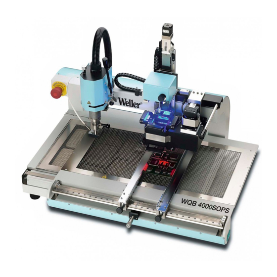
Weller WQB 4000SOPS Operating Instructions Manual
Bga / qfp rework system
Hide thumbs
Also See for WQB 4000SOPS:
- Operating instructions manual (66 pages) ,
- Quick starter manual (9 pages) ,
- Operating instructions manual (64 pages)

Related Manuals for Weller WQB 4000SOPS


Summary of Contents for Weller WQB 4000SOPS
- Page 1 BGA / QFP Rework System WQB 4000SOPS Operating Instructions 1.800.561.8187 information@itm.com www. .com...
- Page 2 1 Table of contents 1.800.561.8187 information@itm.com www. .com...
- Page 3 7.4.1 Soldering profile bar graph ..................33 7.4.2 Input boxes for process parameters ................33 7.4.3 Display LEDs for process step ...................34 7.4.4 Saving and loading parameter blocks / profiles ............35 7.4.5 Soldering / desoldering functions - runtime:..............35 7.4.6 Reinitialisation ......................36 7.4.7 Language selection ....................36 7.4.8 Celsius / Fahrenheit ....................36 7.4.9 Process documentation ....................36 7.6.1 Gradient ........................38...
- Page 4 Have your soldering tool repaired in an electrical service centre......42 8.1.23 Do not work on electrically live parts..............42 8.1.24 Do not connect combustible gases.................42 ® 8.1.25 Use with other WELLER devices................42 8.1.26 Observe the safety regulations applicable to your work area........42 1.800.561.8187 information@itm.com www.
- Page 5 1.800.561.8187 information@itm.com www. .com...
- Page 6 2 Identification Product brand and type designation Product version 1.800.561.8187 information@itm.com www. .com...
- Page 7 Declaration of Conformity 1.800.561.8187 information@itm.com www. .com...
- Page 8 1.800.561.8187 information@itm.com www. .com...
- Page 9 3 Product description General functions, area of application, intended use 1.800.561.8187 information@itm.com www. .com...
- Page 10 Basic device Soldering head 1.800.561.8187 information@itm.com www. .com...
- Page 11 Insertion head Camera and split optical unit Bottom heater PCB holder 1.800.561.8187 information@itm.com www. .com...
- Page 12 Dimensions and weight Specifications on current, gas and compressed air supply 3.10 PC system requirements WIN 2000 SP4 WIN XP SP2, WIN Vista 32-Bit Win 7 32-Bit & 64-Bit 1.800.561.8187 information@itm.com www. .com...
- Page 13 3.11 Noise Emission 3.12 Ambient conditions 3.13 Safety information 1.800.561.8187 information@itm.com www. .com...
- Page 14 4 Definitions 5 Transport and storage 1.800.561.8187 information@itm.com www. .com...
- Page 15 Unpacking Safe disposal of the packaging material 1.800.561.8187 information@itm.com www. .com...
- Page 16 Preparatory task for installation Scope of supply 4000SOPS Control software 1.800.561.8187 information@itm.com www. .com...
- Page 17 Assembly Compress Nitrogen (N 1.800.561.8187 information@itm.com www. .com...
- Page 18 5.5.1.1 Assembly 10 x zoom lens 5.5.1.2 Storing and protecting during interruption of normal usage Repacking to prevent damage during transport 1.800.561.8187 information@itm.com www. .com...
- Page 19 Location of Operating Instructions 6 Operating Instructions Commissioning / restarting This procedure is necessary every time the device is restarted! 1.800.561.8187 information@itm.com www. .com...
- Page 20 Software Installation Registration with Administrator rights is mandatory! The device must not be disconnected To avoid installation conflicts, older software versions should be deinstalled. Especially the SILABS USB driver should be removed 1.800.561.8187 information@itm.com www. .com...
- Page 21 STEP 1 Installation of the SILABS USB drivers SILABS 1.800.561.8187 information@itm.com www. .com...
- Page 22 STEP 2 Installation of the uEye Camera driver 1.800.561.8187 information@itm.com www. .com...
- Page 23 1.800.561.8187 information@itm.com www. .com...
- Page 24 STEP 3 Installation of DirectX 9 1.800.561.8187 information@itm.com www. .com...
- Page 25 STEP 4 Installation of the Weller WQB4000 Control software 1.800.561.8187 information@itm.com www. .com...
- Page 26 Change of the settings of the CPU idle states If you are experiencing performance issues with uEye cameras, please try to change the settings of the CPU idle states. Start the “IDS Camera Manager”. You find this Program in: Start menu/ids/IDS Camera Manager Open the “Additional functions”...
- Page 27 Installation of the firmware updater The installation of the firmware updater is not necessary for correct operation of the device; installation of this software is therefore only recommended if required. Uninstall Back up your parameter blocks or measurement data files before you uninstall the program from your system.
- Page 28 6.10 Program Start 6.11 Checking the split optical unit Placement Important. Following this, the vacuum pick-up alignment must not be changed! 1.800.561.8187 information@itm.com www. .com...
- Page 29 1.800.561.8187 information@itm.com www. .com...
- Page 30 7 Operation Layout and function of operator interface Standard buttons: 1.800.561.8187 information@itm.com www. .com...
- Page 31 Placement 7.3.1.1 Control unit LED Illumination 7.3.1.2 Camera screen and zoom 1.800.561.8187 information@itm.com www. .com...
- Page 32 7.3.1.3 Camera settings 7.3.1.4 Placement / Z-axis drive 7.3.1.4.1.1 Automatic Mode 7.3.1.4.2 Standard mode 1.800.561.8187 information@itm.com www. .com...
- Page 33 Soldering 7.4.1 Soldering profile bar graph 7.4.2 Input boxes for process parameters 1.800.561.8187 information@itm.com www. .com...
- Page 34 7.4.3 Display LEDs for process step 1.800.561.8187 information@itm.com www. .com...
- Page 35 7.4.4 Saving and loading parameter blocks / profiles By loading a parameter block and saving under another name, changed / separate parameter blocks can be created. 7.4.5 Soldering / desoldering functions - runtime: 1.800.561.8187 information@itm.com www. .com...
- Page 36 7.4.6 Reinitialisation 7.4.7 Language selection 7.4.8 Celsius / Fahrenheit 7.4.9 Process documentation 1.800.561.8187 information@itm.com www. .com...
- Page 37 Print Function 1.800.561.8187 information@itm.com www. .com...
- Page 38 Special functions 7.6.1 Gradient During application of Gradient mode, operation is always carried out with nozzle pre- heating and the nozzle is already lowered above the component prior to process start. Nozzle pre-heating (Standby Nozzle) is therefore always activated. 7.6.2 Teach-in 1.800.561.8187 information@itm.com...
- Page 39 7.6.2.1 Automatic Teach-in 7.6.2.2 Manual Teach-In 1.800.561.8187 information@itm.com www. .com...
- Page 40 Other functions 7.7.1 Operating the soldering head and insertion head 7.7.2 Component placement 1.800.561.8187 information@itm.com www. .com...
- Page 41 8 Maintenance and cleaning Safety measures 8.1.1 The mains cable must only be inserted in the approved power sockets or adapters. 8.1.2 Keep your work area tidy and in proper order. 8.1.3 Take surrounding factors into consideration. 8.1.4 Protect yourself against electric shocks. 8.1.5 Keep children away from work area.
- Page 42 8.1.22 Have your soldering tool repaired in an electrical service centre. 8.1.23 Do not work on electrically live parts. 8.1.24 Do not connect combustible gases. ® 8.1.25 Use with other WELLER devices. 8.1.26 Observe the safety regulations applicable to your work area. 1.800.561.8187 information@itm.com...
- Page 43 Maintenance and cleaning by users 1.800.561.8187 information@itm.com www. .com...
- Page 44 Cleaning agents Troubleshooting, fault status diagnosis and repair 1.800.561.8187 information@itm.com www. .com...
- Page 45 1.800.561.8187 information@itm.com www. .com...
- Page 46 Possible faults Fault Cause Remedy 1.800.561.8187 information@itm.com www. .com...
- Page 47 9 Optional modules and extras, specifications 10 Maintenance and cleaning 10.1 Maintenance cycles for safe operation 10.2 Customer Service address Weller Tools GmbH 10.3 Repacking 1.800.561.8187 information@itm.com www. .com...
- Page 48 10.4 Calibration 1.800.561.8187 information@itm.com www. .com...
- Page 49 1.800.561.8187 information@itm.com www. .com...
- Page 50 Camera settings 1.800.561.8187 information@itm.com www. .com...
- Page 51 11 List of spare parts and consumables 11.1 Electrical system 11.2 Pneumatics 11.3 Optical system 1.800.561.8187 information@itm.com www. .com...
- Page 52 11.4 Hot air nozzles Article No. Nozzle housing, inside Nozzle housing, outside 1.800.561.8187 information@itm.com www. .com...
- Page 53 12 De-commissioning the product 13 Warranty 1.800.561.8187 information@itm.com www. .com...
- Page 54 14 Figures 1.800.561.8187 information@itm.com www. .com...
- Page 55 1.800.561.8187 information@itm.com www. .com...
- Page 56 1.800.561.8187 information@itm.com www. .com...
- Page 57 1.800.561.8187 information@itm.com www. .com...
- Page 58 1.800.561.8187 information@itm.com www. .com...
- Page 59 15 Circuit diagrams 1.800.561.8187 information@itm.com www. .com...
- Page 60 1.800.561.8187 information@itm.com www. .com...
- Page 61 17 Index 1.800.561.8187 information@itm.com www. .com...
- Page 62 1.800.561.8187 information@itm.com www. .com...
- Page 63 Parameter block 1.800.561.8187 information@itm.com www. .com...
- Page 64 WIN 2000 SP4 WIN Vista 32-Bit WIN XP SP2 1.800.561.8187 information@itm.com www. .com...
Need help?
Do you have a question about the WQB 4000SOPS and is the answer not in the manual?
Questions and answers