Sign In
Upload
Manuals
Brands
Union Instruments Manuals
Measuring Instruments
CWD2005 Plus
Union Instruments CWD2005 Plus Manuals
Manuals and User Guides for Union Instruments CWD2005 Plus. We have
1
Union Instruments CWD2005 Plus manual available for free PDF download: Original Operating Instructions
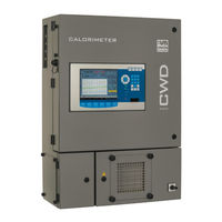
Union Instruments CWD2005 Plus Original Operating Instructions (110 pages)
Combustion Calorimeter
Brand:
Union Instruments
| Category:
Measuring Instruments
| Size: 2 MB
Table of Contents
Table of Contents
3
1 Technical Data
5
Dimensions
5
Fig. 1.1: Housing Dimensions
5
Device Overview
6
Voltage Supply
6
Interfaces
6
Fig. 1.2: Markings and Warning Information
6
Display Times of Combustion Value Measurement
7
Gas Inputs
7
Calibration Gas / Test Gas
7
Process Gas
8
Linearity and Measuring Ranges
8
Environmental Conditions
9
2 EU Declaration of Conformity
11
3 Safety Information
13
Warning Information and Symbols
13
Principle, Intended Use
14
Personnel and Qualification
14
Safety Information
15
General Safety Information
15
Information on Specific Hazards
15
Note on Explosion Protection
16
Safety Precautions on the Owner Side
16
Recurring Operator Training
17
Performing a Workplace Hazard Analysis
17
4 Protective Equipment
19
Main Switch
19
Safety Switch
19
Fig. 4.1: Main Switch (Example)
19
Fig. 4.2: Figure Safety Switch (Example)
19
Thermal Cutoff
20
Solenoid Valve
20
Fan
20
Door Enclosure
20
Markings and Warning Information
21
Fig. 4.3: Markings and Warning Information (Example)
21
Fig. 4.4: Warning Information on Electrical Connection Plate (Example)
21
5 Description and Connections
23
Enclosure Connections Outside
23
Fig. 5.1: Housing Connections
23
Connections and Components Inside
25
Fig. 5.2: Housing Without Doors, Example
25
Accessories
26
6 Transport, Installation, and Acceptance
27
Transport
27
Environmental Conditions
28
Storage Conditions
28
Installing and Connecting
29
Installation Location
29
Room Ventilation
30
Wall Mounting
31
Fig. 6.1: Wall Mounting
32
Fig. 6.2: Dimensions Wall Mounting
32
Process Gas
33
Carrier Gas Supply
34
Calibration Gas
35
Flue Gas
36
Electrical Connection
37
Fig. 6.3: Electrical Connection Plate, Example
37
Electrical Interfaces
38
Fig. 6.4: USB Interface on the Left Side of the Housing
38
Connector Assignment Input-Output Ioexternal
39
Fig. 6.5: Connector Assignment Input-Output IO Type 06
39
Commissioning after Installation
42
Removing/Attaching Transport Securing Devices
43
Fig. 6.6: Transport Securing Devices
43
Documentation
44
Fig. 6.7: Transport Securing Devices of Pressure Controller
44
7 Commissioning/Switching on
45
8 Description of the Work Stations/Operator Control Elements
47
Fig. 8.1: Work Stations
47
9 Operation
49
Operation of Membrane Keyboard/Description of Display
49
Fig. 9.1: Operator Control Elements/Structure of Display
49
Basic Operation
51
Available Displays
51
General Information
52
Fig. 9.2: General Information
52
Menu Structure
53
Main Menu
54
Main Menu - Options
55
Main Menu - Options - I/O
56
Main Menu - Options - I/O - Analog Outputs
57
Main Menu - Options - I/O - Digital Outputs
58
Main Menu - Options - I/O - Ma Display
60
Main Menu - Options - I/O - Digital Inputs
61
Main Menu - Options - I/O - Display
62
Main Menu - Options - Calibration
63
Main Menu - Options - Calibration - Configuration of Calibration Gas
64
Main Menu - Options - Calibration - Automatic Calibration
65
Main Menu - Options - Calibration - Automatic Calibration 2
66
Main Menu - Options - Calibration - Calibration
66
Main Menu - Options - Calibration - Save Base Calibration
66
Main Menu - Options - Calibration - Calibration Limits
67
Main Menu - Options - System
68
Main Menu - Options - System - General
69
Main Menu - Options - System - Ignition
71
Main Menu - Options - System - CSV Export
72
Main Menu - Options - System - Hold Signal On/Off
72
Main Menu - Options - System - Load Factory Settings
72
Main Menu - Options - System - Settings
73
Main Menu - Options - System - Settings - Date / Time
73
Main Menu - Options - System - Settings - Language
74
Main Menu - Options - System - Settings - Password
75
Main Menu - Options - System - Settings - Change Color
76
Main Menu - Options - System - Settings - Hardware 1
77
Main Menu - Options - Service
79
Main Menu - Trend
80
Main Menu - Graphic - Select Time
81
Main Menu - Graphic - Select Value
82
Main Menu - Graphic - Select Signal
83
Main Menu - Graphic - Select Unit
83
Main Menu - Graphic - Select Curve
84
Main Menu - Event List
85
Main Menu - Device Information
86
10 Decommissioning / Switching off
89
11 Maintenance
91
Preparations
91
Maintenance Work/Inspection
92
12 Troubleshooting
95
Preparations for Troubleshooting
96
Changing/Replacing Fuses
97
Unstable Measured Value
97
Drift of Measured Value
97
Incorrect Ignition
97
Error/Status Messages
98
13 Service
101
14 Disposal
103
15 Spare Parts
105
16 Appendix
107
Data Structure Profibus
107
Table 1: Data Structure Profibus
107
Data Struture Serial Interface RS 232 (Option)
108
Index
109
List of Figures/List of Tables
110
List of Figures
110
List of Tables
110
Advertisement
Advertisement
Related Products
Union Instruments CWD 2005
Union Instruments CWD2000 EX
Union Instruments CWD3000 EXP
Union Instruments CWD
Union Instruments CWD Plus
Union Instruments CWD2005 SPC
Union Instruments INCA 1000
Union Instruments INCA 2000
Union Instruments INCA 3000
Union Instruments INCA 4000
Union Instruments Categories
Measuring Instruments
Accessories
Control Systems
More Union Instruments Manuals
Login
Sign In
OR
Sign in with Facebook
Sign in with Google
Upload manual
Upload from disk
Upload from URL