Moxa Technologies POS-104UL Quick Installation Manual
4-port rs-232 universal pci serial board
Hide thumbs
Also See for POS-104UL:
- User manual (141 pages) ,
- User manual (100 pages) ,
- Quick installation manual (4 pages)
Advertisement
POS-104UL
Quick Installation Guide
First Edition, January 2007
1. Overview
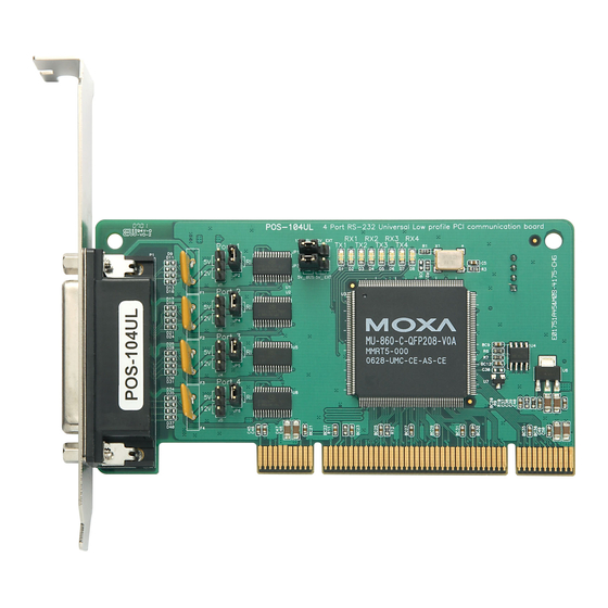
The POS-104UL is a 4-port RS-232 Universal PCI serial board that is
ideal for connecting a wide range of serial devices to a PC. Suitable
devices include terminals, modems, printers, scanners, cash registers, bar
code readers, keypads, numeric displays, electrical scales, and data
acquisition equipment. The board's device drivers make full use of the
128-byte Tx/Rx FIFO and on-chip H/W and S/W flow control, which
allow data transmission at speeds of up to 921.6 Kbps.
2. Package Checklist
Before installing the POS-104UL board, verify that the package contains
the following items:
1 POS-104UL 4-port RS-232 with serial port power board
Document and Software CD-ROM
POS-104UL Quick Installation Guide
Low Profile Bracket
5-year Product Warranty Statement
Please notify your sales representative if any of the above items are
missing or damaged.
3. Hardware Installation Procedure
The POS-104UL board MUST be installed in the PC before installing the
driver. The following directions explain how to install the board in the
PC.
— 1 —
STEP 1: Power off the PC.
STEP 2: Insert the POS-104UL control board firmly into a free PCI or
PCI-X slot.
STEP 3: Fasten the holding screw to fix the control board in place.
STEP 4: Use the jumpers on the board to select the source of the serial
port power.
a. Configure the jumpers labeled "Step a" below to select the
b. Jumper pins for each of the 4 ports are provided to select RI,
STEP 5: Power on the PC; the BIOS will set the IRQ and I/O address
automatically.
P/N: 1802001048000
source of the port power. 5V and 12V power can be
configured independently. Use the top row of pins to select
the 12V power source, and use the bottom row of pins to
select the 5V power source. Short the left two pins of the row
to select Bus power, and short the right two pins of the row to
select external power. If one or both of the rows are set for
external power, you need connect the cable from the back of
POS-104UL to the PC's power supply.
5V, or 12V as the power signal for that port (see the pins
labeled "Step b" below).
> Short the right two pins to set pin 9 of that port as the RI
signal (input).
> Short the top two pins on the left to set pin 9 of that port as
the 5V power output.
> Short the bottom two pins on the left to set pin 9 of that
port as the 12V power output.
Step a
Step b
12V_BUS12V_EXT
Port 1
JP1
5V
RI
JP3
12V
JP2
5V_BUS 5V_EXT
J1
Port 2
5V
RI
12V
JP4
J2
Port 3
5V
RI
MU860
12V
JP5
J4
Port 4
5V
RI
12V
JP6
J5
— 2 —
4. Software Installation Information
The board MUST be plugged in before installing the driver software. See
the previous section for instructions on how to install the board in your
PC. Refer to the POS-104UL User's Manual for detailed instructions on
installing the drivers for this board.
Windows 2003/XP Driver Installation
1. After powering on your PC, Windows 2003/XP will detect the
POS-104UL board automatically.
2. Insert the POS-104UL software CD in your CD-ROM drive.
3. Select Install from a list or specific location (Advanced).
4. After selecting Search for the best driver in these locations, check
the Include this location in the search checkbox, and then use the
browse button to navigate to the CD's
\Software\Windows XP-2003 folder.
5. Click Continue Anyway in response to any warnings that the
software hasn't passed Windows Logo testing.
6. After the board has been installed, the installation wizard will guide
you through the port installation procedure, starting with port 0.
7. Use the Device Manager to check if the installation of the board and
ports was successful. Click on the + sign next to Hardware, and then
check under Multi-port serial adapters and Ports (COM & LPT). If
there are any special marks, such as a question mark or exclamation
point, in front of the board or port icons, examine the Event Log as a
first step to determine where the problem is.
Windows 2000 Driver Installation
1. After powering on your PC, Windows 2000 will detect the
POS-104UL board automatically.
2. Insert the POS-104UL software CD in your CD-ROM drive.
3. Select Search for a suitable driver for my device (recommended).
4. In Optional search location, checkmark specify a location. Navigate
to the \Software\Windows 2K folder on the software CD, and then
click on OK to continue.
5. Click Continue Anyway in response to any warnings that the
software hasn't passed Windows Logo testing.
6. After the board has been installed, the installation wizard will guide
you through the port installation procedure, starting with port 0.
NOTE: Be sure to install the software from the CD's
\Software\Windows 2K folder.
7. Use the Device Manager to check if the installation of the board and
ports was successful. Click on the + sign next to Hardware, and then
check under Multi-port serial adapters and Ports (COM & LPT). If
there are any special marks, such as a question mark or exclamation
point, in front of the board or port icons, examine the Event Log as a
first step to determine where the problem is.
— 3 —
Advertisement
Table of Contents

Related Manuals for Moxa Technologies POS-104UL


Summary of Contents for Moxa Technologies POS-104UL
- Page 1 4. Software Installation Information STEP 1: Power off the PC. STEP 2: Insert the POS-104UL control board firmly into a free PCI or The board MUST be plugged in before installing the driver software. See PCI-X slot. the previous section for instructions on how to install the board in your POS-104UL STEP 3: Fasten the holding screw to fix the control board in place.
- Page 2 5. Pin Assignments and Cable Wiring POS-104UL boards have one female DB44 connector on the board. You may use the cable included as a standard accessory to connect to your serial devices, we give the pin assignments for the serial device side.
Need help?
Do you have a question about the POS-104UL and is the answer not in the manual?
Questions and answers