Festo SPC11 Series Quick Reference
Soft stop
Hide thumbs
Also See for SPC11 Series:
- Supplementary manual (88 pages) ,
- User instructions (74 pages) ,
- Supplementary description (40 pages)
Advertisement
Quick Links
Advertisement

Related Manuals for Festo SPC11 Series


Summary of Contents for Festo SPC11 Series
- Page 1 Soft Stop SPC11 Quick reference Soft Stop type SPC11-... – English 8103866 2018-12b [8103868]...
- Page 2 Translation of the original instructions Documentation on the product For all available product documentation è www.festo.com/pk Copyright: Festo SE & Co. KG Ruiter Straße 82 73734 Esslingen Germany Internet: http://www.festo.com E-Mail: service_international@festo.com Reproduction, distribution or sale of this document or communication of its contents to others without express authorization is prohibited.
- Page 3 Always switch on the operating voltage supply first and then the compressed air supply. Before carrying out installation and/or maintenance work, switch off the following power supplies either simultaneously or in the following sequence: 1. compressed air supply 2. operating voltage for the SPC11. Festo SPC11 2018-12b English...
-
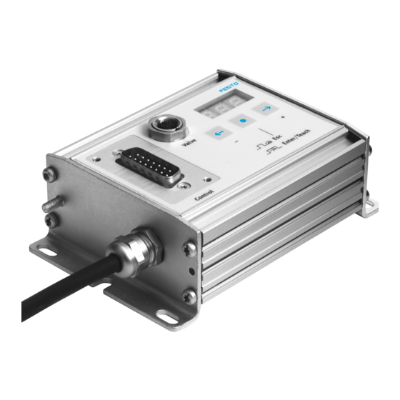
Page 4: Connecting And Display Elements
Connecting and display elements Control: operating voltage Type plate connection and I/O coupling Groove for identification Valve: Valve connection signs (type IBS 6x10) Display Measuring system connection (here type Operating buttons SPC11-POT-TLF) Earth (ground) connection Festo SPC11 2018-12b English... - Page 5 Fit silencers with large rated flow (e.g. U-1/8), length of tubing max. 1 m. Compressed air tubing and screw connectors The tubing for the valve drive must be symmetrical. With linear drives: tubing length = drive length Festo SPC11 2018-12b English...
- Page 6 Do not use any restrictors in the supply lines. Drive and measuring system Use only the permitted combinations of valves, drives and measuring systems approved of by Festo for the SPC11. Observe the permitted fitting positions. Mount the measuring system symmetrical to the drive stroke.
- Page 7 Use fixed stops to limit the working stroke. With drives of type DGP(I)(L)-..., the working stroke should not project into the range of the end position cushioning. Mass load Fasten the permitted mass load to the slide without play. Festo SPC11 2018-12b English...
- Page 8 When compressed air is applied to work connection 2, movement is made in the opposite direction. With linear drives: the zero point of the measur ing system lies on the side of the measuring system con nection. Festo SPC11 2018-12b English...
- Page 9 With linear drives, end connection with core colours position 1 lies on the side for cable KMPV-SUB-D-15-... with the electrical O..: output, I..: Input connections to the measuring system. Button for moving to the positions Earth/ground Festo SPC11 2018-12b English...
- Page 10 50 ms when the drive moves past O3: P.03 the appropriate position. O4: P.04 O5: Error Supplies a 1-signal if there is an error. O..: Output Can be configured; P.04 (factory setting) or Stop Can be configured; Error (factory setting) or Ready Festo SPC11 2018-12b English...
- Page 11 I7: {/– E8: Remote 1-signal deactivates operating buttons and activates the relevant inputs (pins 2...4) I..: Input Can be configured; P.04 (factory setting) or Stop 0-signal at input E8 (Remote) required Connection Description Power supply 24 V Festo SPC11 2018-12b English...
- Page 12 2. Switch on the operating voltage supply. 3. Check the parameters shown after switching on. 4. Finally, switch on the compressed air supply. The valve slide assumes the mid-position. The drive can move slowly into one of the end positions. Festo SPC11 2018-12b English...
- Page 13 In order to avoid damage due to uncushioned move ment into the end positions: ‒ Carry out commissioning again if the fixed stops have been adjusted or if components have been replaced. ‒ Observe the maximum permitted mass load. Festo SPC11 2018-12b English...
-
Page 14: Instructions On Operation
Adapt the amplification or cushioning stage. If necessary, fit restrictors in the exhaust tubing of the MPYE-5-... in order to reduce speed. Festo SPC11 2018-12b English...
Need help?
Do you have a question about the SPC11 Series and is the answer not in the manual?
Questions and answers