Sign In
Upload
Download
Table of Contents
Contents
Add to my manuals
Delete from my manuals
Share
URL of this page:
HTML Link:
Bookmark this page
Add
Manual will be automatically added to "My Manuals"
Print this page
×
Bookmark added
×
Added to my manuals
Manuals
Brands
Festo Manuals
Controller
SPC11-POT-TLF
System manual
Festo SPC11-POT-TLF System Manual
Soft stop
Hide thumbs
1
2
3
4
Table Of Contents
5
6
7
8
9
10
11
12
13
14
15
16
17
18
19
20
21
22
23
24
25
26
27
28
29
30
31
32
33
34
35
36
37
38
39
40
41
42
43
44
45
46
47
48
49
50
51
52
53
54
55
56
57
58
59
60
61
62
63
64
65
66
67
68
69
70
71
72
73
74
75
76
77
78
79
80
81
82
83
84
85
86
87
88
89
90
91
92
93
94
95
96
97
98
99
100
101
102
103
104
105
106
107
108
109
110
111
112
113
114
115
116
117
118
119
120
page
of
120
Go
/
120
Contents
Table of Contents
Bookmarks
Table of Contents
Table of Contents
Intended Use
Service
Target Group
Important User Instructions
Product-Specific Terms and Abbreviations
Notes on the Use of this Manual
1 Summary of Components
Structure
Method of Operation
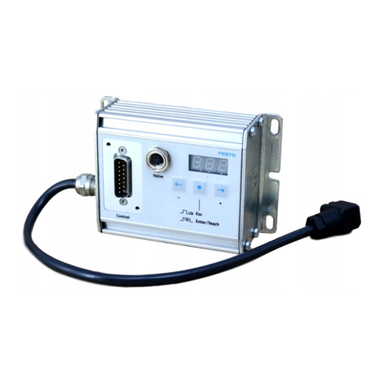
Display and Connecting Elements on the SPC11
2 Fitting
Fitting the SPC11
3 Installation
General Instructions on Installation
Installation
Notes on Installing the Pneumatic Components
Pneumatic Emergency Stop Circuit
Fitting the Electronic Components
Connecting Elements on the SPC11
Connecting the Power Supply and the I/Os
Connecting the Proportional Directional Control Valve and the Measuring System
4 Commissioning
General Instructions on Commissioning
Basic Principles of Configuring and Operating the SPC11
Commissioning
General Instructions on Commissioning
Pre-Parametrizing Without the Drive in the Office
Modify Parameter
Proceed as Follows When Commissioning
Preparations for the Teach Procedure
Start the Teach Procedure
Teaching MID-Positions
Conclude Teach Procedure
Carry out the Teach Procedure Again
Notes on Operation
Switching-On Behaviour after Successful Commissioning
The First Positioning Task
Controlling the SPC11
Using the Taught MID-Position as a Sensor Position
5 Diagnosis and Error Treatment
Error Messages on the SPC11
Diagnosis and Error Treatment
Faults During Operation
Optimizing the Positioning Behaviour
Commissioning Via Digital Inputs/Outputs
The Remote Inputs of the SPC11
Instructions on Commissioning Via Digital Inputs/Outputs
A.1 the Remote Inputs of the SPC11
A.2 Instructions on Commissioning Via Digital Inputs/Outputs
Set Time Diagram for Parameters
Introduce and Start the Time Diagram for the Teach Procedure
Time Diagram Teach MID-Position
Technical Appendix
B. Technical Appendix
Technical Specifications
B.1 Technical Specifications
Index
B.2 Index
Advertisement
Quick Links
1
Basic Principles of Configuring and Operating the Spc11
2
Modify Parameter
3
Start the Teach Procedure
4
Error Messages on the Spc11
Download this manual
SPC11 Soft Stop
Electronics/
pneumatics
manual
System manual
Soft Stop
type SPC11-...-...
Manual
196 724
en 0205a
[664 851]
Table of
Contents
Previous
Page
Next
Page
1
2
3
4
5
Advertisement
Table of Contents
Need help?
Do you have a question about the SPC11-POT-TLF and is the answer not in the manual?
Ask a question
Questions and answers
Related Manuals for Festo SPC11-POT-TLF
Controller Festo SPC11 Supplementary Manual
(88 pages)
Valve Positioners Festo SPC11 Series User Instructions
Soft stop (74 pages)
Industrial Equipment Festo SPC11 Supplementary Description
Soft stop (40 pages)
Controller Festo SPC11 Series Quick Reference
Soft stop (14 pages)
Controller Festo SPC11-POT-LWG System Manual
Soft stop (120 pages)
Controller Festo SPC10-POT 2 Series Quick Reference
Soft stop (51 pages)
Controller Festo SPC-10 Series Quick Reference
Smart soft stop (50 pages)
Controller Festo SPC-10 Manual
Smart soft stop electronic/pneumatic (115 pages)
Controller Festo SPC200 User Instructions
Smart positioning controller (62 pages)
Controller Festo SPC200 Series Quick Reference
(22 pages)
Controller Festo SPC200 Manual
Smart positioning controller (126 pages)
Controller Festo SPC200 System Manual
Smart positioning controller (506 pages)
Controller Festo SPC200 Electronic Manual
Smart positioning controller. stepping motor indexer module type spc200-smx-1 (103 pages)
Controller Festo SPC200 Quick Reference
Smart positioning controller (62 pages)
Controller Festo SPC200 Manual
Positioning system, smart positioning controller (369 pages)
Controller Festo SPC200 Series Short Description
Smart positioning controller (62 pages)
This manual is also suitable for:
Spc11-pot-lwg
Spc11 series
Spc11-mts-aif
Table of Contents
Print
Rename the bookmark
Delete bookmark?
Delete from my manuals?
Login
Sign In
OR
Sign in with Facebook
Sign in with Google
Upload manual
Upload from disk
Upload from URL


Need help?
Do you have a question about the SPC11-POT-TLF and is the answer not in the manual?
Questions and answers