Westermo DDW-142-12VDC-BP User Manual
Industrial ethernet extender
Hide thumbs
Also See for DDW-142-12VDC-BP:
- User manual (21 pages) ,
- User manual (21 pages) ,
- User manual (23 pages)
Table of Contents
Advertisement
Quick Links
Advertisement
Table of Contents

Related Manuals for Westermo DDW-142-12VDC-BP


Summary of Contents for Westermo DDW-142-12VDC-BP
- Page 1 www.wester mo.com DDW-142/242-12VDC-BP Industrial Ethernet Extender...
-
Page 2: Table Of Contents
Table of Contents 1. General Information ................ 3 1.1. Legal Information ..............3 1.2. About This Guide ..............3 1.3. Software Tools ..............3 1.4. License and Copyright for Included FLOSS ......... 3 1.5. WeOS Management Guide ............3 2. Safety and Regulations ..............4 2.1. -
Page 3: General Information
Westermo reserves the right to revise this document or withdraw it at any time without prior notice. Under no circumstances shall Westermo be responsible for any loss of data or income or any special, incidental, and consequential or indirect damages howsoever caused. -
Page 4: Safety And Regulations
2. Safety and Regulations 2.1. Warning Levels Warning signs are provided to prevent personal injuries and/or damages to the product. The following levels are used: Level of warning Description Consequence Consequence personal injury material damage Indicates a potentially Possible death or major Major damage to the hazardous situation injury... -
Page 5: Safety Information
WARNING - PROTECTIVE FUSE It must be possible to disconnect manually from the power supply. Ensure compliance to national installation regulations. Replacing the internal fuse must only be performed by Westermo qualified personell. WARNING - POWER SUPPLY CONNECTION There are safety regulations on which power sources that shall be used in conjunction with the product. -
Page 6: Care Recommendations
If the product is used in a manner not according to specification, the protection provided by the equipment may be impaired. If the product is not working properly, contact the place of purchase, nearest Westermo distributor office or Westermo technical support. -
Page 7: Product Disposal
2.4. Product Disposal This symbol means that the product shall not be treated as unsorted municipal waste when disposing of it. It needs to be handed over to an applicable collection point for recycling electrical and electronic equipment. By ensuring the product is disposed of correctly, you will help to reduce hazardous substances and prevent potential negative consequences to both environment and human health, which could be caused by inappropriate disposal. -
Page 8: Corrosive Environment
2.5.4. Simplified Declaration of Conformity Hereby, Westermo declares that this product is in compliance with applicable EU directives. The full EU declaration of conformity and other detailed information is available at www.westermo.com/support/product-support. -
Page 9: Product Description
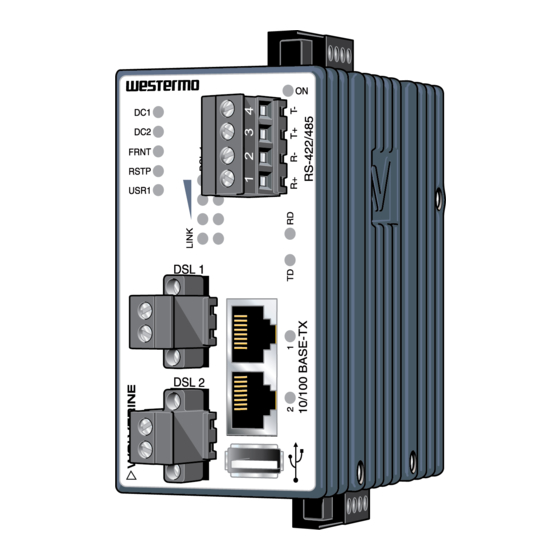
3. Product Description 3.1. Product Description The Wolverine DDW-142/242-12VDC-BP with bypass relay allows effective Ethernet networks to be created over long distances up to 15 km (9.3 mi) at data rates up to 15.3 Mbit/s on a single twisted pair cable. By using two pairs “bonded” this rate can be doubled up to 30.6 Mbit/s. -
Page 10: Available Models
In case of power loss, maximum distance has to be calculated. 3.2. Available Models Art. no. Model 100 Mbit SHDSL Serial Software Rated ports ports voltage ports 3642-0440 DDW-142-12VDC-BP 12-48 VDC 3642-0450 DDW-242-12VDC-BP 12-48 VDC 3.3. Connector Information 3.3.1. Power Input Illustration Position Product marking Direction Description +DC1 Input... -
Page 11: Shdsl Connection
3.3.3. SHDSL Connection Illustration Pin no. Direction Description In/Out 2-wire Receive/Transmit SHDSL In/Out 2-wire Receive/Transmit SHDSL Table 5. SHDSL connection 3.3.4. I/O Connection Illustration Pin no. Product marking Direction Description Status + Output Status relay contact (alarm) Status - Output Status relay contact (alarm) Digital in + Input... -
Page 12: Usb Connection
1. Connect the serial diagnostic cable to the console port (use only Westermo cable 1211-2027). 2. Connect cable to your computer (USB port, if drivers are needed they can be downloaded from the Westermo web). 3. Use a terminal emulator and connect with correct speed and format (115200, 8N1) to the assigned port. -
Page 13: Led Indicators
3.4. LED Indicators Status Description Product has no power GREEN All OK, no alarm condition Alarm condition, or until product has started up. (Alarm conditions are configurable, see WeOS Management Guide) BLINK Location indicator ("Here I am!"). Activated when connected to WeConfig tool, or upon request from web or/and CLI. -
Page 14: Dimensions
Status Description No serial data transmitted GREEN FLASH Serial data transmitted YELLOW Indicates error on RS-422/845 bus FLASH Ethernet port 1 No link to 2 GREEN Link established GREEN FLASH Data traffic indication YELLOW Port alarm and no link. Or if FRNT, RSTP or Link Aggregation mode, port is blocked. -
Page 15: Installation
4. Installation 4.1. Mounting This product should be mounted on a 35 mm DIN-rail, which is horizontally mounted inside an apparatus cabinet or similar. It is recommended that the DIN-rail is connected to ground. Snap on the product to the DIN-rail according to the figure. Figure 5. -
Page 16: Cooling
This product runs the Westermo Operating System (WeOS) which provides several management tools that can be used for configuration of the unit. • WeConfig tool This is a custom Westermo tool used for discovery of attached Westermo product. • Web Configuration of the product using the web browser. -
Page 17: Configuration Via A Web Browser
Username: admin Password: westermo Once logged in, use the extensive integrated help function describing all configuration options. Two common task when configuring a new switch is to assign appropriate IP settings, and to change the password of the admin account. - Page 18 • Acknowledge that you wish to conduct the factory reset by unplugging the Ethernet cables. The ON LED will stop flashing. This initiates the factory reset process and the product will restart with factory default settings. When the product has booted up, the ON LED will show a green light and is now ready to use.
-
Page 19: Specifications
5. Specifications 5.1. Interface Specifications DC, Power port Rated voltage 12 - 48 VDC Operating voltage 9.8 - 60 VDC Rated current 475 mA (765 mA) at 12 VDC (with 500 mA USB load) 245 mA (405 mA) at 24 VDC (with 500 mA USB load) 124 mA (200 mA) at 24 VDC (with 500 mA USB load) Rated frequency Inrush current, I²t... - Page 20 Ethernet TX Electrical specification IEEE std 802.3 Data rate 10 Mbit/s, 100 Mbit/s, manual or auto Duplex Full or half, manual or auto Circuit type TNV-1 Transmission range Up to 150 m with CAT5e cable or better Isolation To all other ports Connection RJ-45, auto MDI/MDI-X Cabling...
- Page 21 USB receptacle connector type A Console port Electrical specification LVTTL/LVCMOS-level Data rate 115.2 kbit/s Circuit type SELV Data format 8 data bits, no parity, 1 stop bit, no flow control Connection 2.5 mm jack, use only Westermo cable 1211-2027 DDW-142/242-12VDC-BP...
- Page 22 SHDSL Electrical specification ITU-T G.991.2 Annex B Data rate 32 kbit/s to 30.4 Mbit/s with bonding Protocol EMF according to IEEE 802.3 Data format According to ITU-T G.991.2, depending on line quality Isolation To all other ports Connection Detachable screw terminal Conductor cross section 0.2 - 2.5 mm (AWG 24 - 13)
-
Page 23: Type Tests And Environmental Conditions
5.2. Type Tests and Environmental Conditions Environmental Basic standard Description Test levels phenomena EN 61000-4-2 Enclosure Contact: ±6 kV Air: ±8 kV Fast transients EN 61000-4-4 Power port ± 2 kV Ethernet ports SHDSL ports RS-232 port Status out/Digital in Earth port ±... - Page 24 Environmental Basic standard Description Test levels phenomena Ethernet ports to all 1.5 kVrms, 1 min other isolated ports RS-232 port to all other isolated ports SHDSL ports to all other isolated ports Status out/Digital in port to all other isolated ports Table 11.
-
Page 25: Revision Notes
Change description Rev. E 2020-11 Westermo logo updated, illustrations updated from brown to blue, new information structure throughout the manual, 2 Safety and Regulations - entire chapter updated, 4.1 Mounting updated, 4.2 Removal of Product updated, 5.1 Interface Specifications updated, 5.2 Type Tests and... - Page 26 DDW-142/242-12VDC-BP...
- Page 27 DDW-142/242-12VDC-BP...
- Page 28 Westermo • SE-635 35 Stora Sundby, Sweden Tel +46 16 42 80 00 Fax +46 16 42 80 01 E-mail: info@westermo.com www.westermo.com 6642-22541 REV. E 2020 11 Westermo Network Technologies AB, Sweden...
Need help?
Do you have a question about the DDW-142-12VDC-BP and is the answer not in the manual?
Questions and answers