Table of Contents
Advertisement
Quick Links
Advertisement
Table of Contents

Related Manuals for Westermo DDW-100


Summary of Contents for Westermo DDW-100
- Page 1 User Guide DDW-100 6621-2202 Industrial Ethernet SHDSL Extender www.westermo.com...
-
Page 2: Legal Information
Under no circumstances shall Westermo be responsible for any loss of data or income or any special, incidental, and consequential or indirect damages howsoever caused. -
Page 3: Care Recommendations
Do not use or store the unit in dusty, dirty areas, connectors as well as other mechanical part may be damaged. If the unit is not working properly, contact the place of purchase, nearest Westermo dis- tributor office or Westermo Tech support. -
Page 4: Agency Approvals And Standards Compliance
Agency approvals and standards compliance Type Approval / Compliance EN 61000-6-2, Immunity industrial environments EN 55024, Immunity IT equipment EN 61000-6-3, Emission residential environments FCC part 15 Class B EN 50121-4, Railway signalling and telecommunications apparatus IEC 62236-4, Railway signalling and telecommunications apparatus Safety EN 60950-1, IT equipment UL listed, UL 60950-1... - Page 5 Declaration of Conformity Westermo Teleindustri AB Declaration of conformity The manufacturer Westermo Teleindustri AB SE-640 40 Stora Sundby, Sweden Herewith declares that the product(s) Type of product Model Art no User guide DIN-rail DDW-100 3621-0002 6621-2202 is in conformity with the following EC directive(s).
-
Page 6: Type Tests And Environmental Conditions
Type tests and environmental conditions Electromagnetic Compatibility Phenomena Test Description Level ESD * EN 61000-4-2 Enclosure contact ± 6 kV Enclosure air ± 8 kV RF field AM modulated * IEC 61000-4-3 Enclosure 10 V/m 80% AM (1 kHz), 80 – 1 000 MHz 20 V/m 80% AM (1 kHz), 80 –... -
Page 7: Functional Description
Functional description SHDSL represents the best of several symmetric DSL technologies that have been com- bined into a single industry standard.The DDW-100 is designed as a transparent Ethernet Extender (Ethernet Bridge) for 10/100BaseTX networks. It is transparent for multicast addressing,VLAN packets,VPN pass-through for IPSec and for protocols like MODBUS/tcp and Profinet. -
Page 8: Getting Started
Getting started The DDW-100 is easy to use and install, the units work in pairs, one as has to be config- ured as CO (Central Office) and one as CPE (Customer Premises Equipment).This con- figuration is made with DIP-switches situated under the lid of the DDW-100. -
Page 9: Diagnostic Information
Diagnostic information: The DDW-100 can display diagnostic information using a terminal. program 1) Connect a Westermo standard cable 1211-2026 (two metre 9-pole D-sub) to the RS-232 interface located under lid. 1211-2026 RS-232 2) Open a terminal program with settings: Data rate: 115.2 kbit/s... -
Page 10: Interface Specifications
Interface specifications Power Rated voltage 12 to 48 VDC Operating voltage 10 to 60 VDC Rated current 290 mA @ 12 VDC 140 mA @ 24 VDC 80 mA @ 48 VDC Rated frequency Inrush current, I 0.098 A Startup current 0.6 A peak Polarity... - Page 11 Circuit type SELV Transmission range 15 m Isolation to All other Connection Westermo cable 1211-2066 Ethernet TX Electrical specification IEEE std 802.3. 2000 Edition Data rate 10 Mbit/s, 100 Mbit/s, manual or auto Duplex Full or half, manual or auto...
- Page 12 Position Description should be used. No. 1 Common No. 2 The DDW-100 supports redundant power connec- tion.The positive input are +VA and +VB, the nega- No. 3 tive input for both supplies are COM. The power is No. 4 Common drawn from the input with the highest voltage.
-
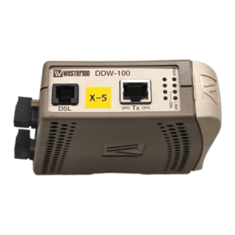
Page 13: Led Indicators
LED Indicators Status Indication of Unit has no power Internal power Slow flash Initialisation progressing Fast FLASH Initialisation error DSL * Unit is unconnected Flash 1 (200 ms) Unit is initializing DSL, only CO Flash 2 (400 ms) Unit is in activation phase 1of DSL link establishment Flash 3 (1 s) Unit is in activation phase 2 of DSL link... -
Page 14: Dip Switch Settings
DIP-switch settings Before DIP-switch settings: Prevent damage to internal electronics from electrostatic discharges (ESD) by discharging your body to a grounding point (e.g. use of wrist strap). NOTE DIP-switch alterations are only effective after a power on. A setting configured by any other method during normal operation, overrides the DIP-switch setting. - Page 15 Annex B enabled, normal mode Description of normal, high-speed and reliable mode With SW2:2, 3 the DDW-100 is set to reliable, high-speed or normal mode. Choose mode depending on your application, if you wish to transmit large amounts of non critical data, choose high-speed mode with a noise margin 0 dB.
- Page 16 Mounting This unit should be mounted on 35 mm DIN-rail, which is horizontally mounted inside an apparatus cabinet, or similar. Snap on mounting, see figure. Cooling 10 mm * (0.4 inches) This unit uses convection cooling.To avoid obstructing the air- 25 mm flow around the unit, use the following spacing rules.
-
Page 17: Block Diagram
Application Block diagram Diagn. Port 4-& 8-pos. DIP Switch Ethernet Interface Isolation RJ-45 Connector SHDSL modem Memory Power SHDSL Power Link Isolation Interface RJ-12 Connector Screw Screw Connector Connector DDW-100 as an transparent Ethernet extender Ethernet Ethernet 6621-2202... - Page 20 Tél : +33 1 69 10 21 00 • Fax : +33 1 69 10 21 01 Phone: +44(0)1489 580 585 • Fax.:+44(0)1489 580586 E-mail : infos@westermo.fr E-Mail: sales@westermo.co.uk Westermo Teleindustri AB have distributors in several countries, contact us for further information.
Need help?
Do you have a question about the DDW-100 and is the answer not in the manual?
Questions and answers