
Related Manuals for Parker K Series


Summary of Contents for Parker K Series
- Page 1 Servomotors K Series Kit - CE Certified Technical Manual PVD 3674_GB 1 - PVD 3674_GB_K Series_CE-November 2016.Docx...
- Page 2 40° C in the vicinity of the motor flange. As K Series are the active parts of an incomplete motor, the design, the construction, the certification and the final conformance of the complete motor is under the responsibility of the integrator.
-
Page 3: Table Of Contents
Table of Content INTRODUCTION ............................5 1.1. Purpose and intended audience ....................... 5 1.2. Safety ..............................5 1.2.1. Principle ............................ 5 1.2.2. General Safety Rules ....................... 6 PRODUCT DESCRIPTION ........................7 2.1. Quick URL ............................7 2.2. Overview ............................7 2.3. - Page 4 4.6. Troubleshooting ..........................65 Lexicon in use Kit: Active parts delivered by Parker Motor: Active parts integrated into a mechanical assembly providing the means of rotating, designed, assemblied, certified and tested according to the relevant directives, standard, regulation for the motor application...
-
Page 5: Introduction
If any malfunction or technical problem occurs, that has not been dealt with in this manual, please contact PARKER for technical assistance. In case of missing information or doubts regarding the installation procedures, safety instructions or any other issue tackled in this manual, please contact PARKER as well. -
Page 6: General Safety Rules
1.2.2. General Safety Rules Generality DANGER: The installation, commission and operation must be performed by qualified personnel, in conjunction with this documentation. The qualified personnel must know the safety (C18510 authorization, standard VDE 0105 or IEC 0364), the standard to comply with the low directive and the EMC directive and local regulations such as Machinery Directive 2006/42/EC They must be authorized to install, commission and operate in accordance... -
Page 7: Product Description
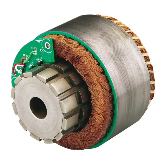
The K frameless servomotor are the active parts of a servo motor: a rotor and a stator. The K series can not be used alone and must integrated into a complete system to provide a complete servomotor. The design, the construction, the certification and the tests are the responsibility of the integrator. -
Page 8: Motor Description
2.4. Motor description 8 - PVD 3674_GB_K Series_CE-November 2016.Docx... -
Page 9: General Technical Data
2.5. General Technical Data Motor type Permanent-magnet synchronous motor Magnet material Nd-Fe-B (Neodymium Iron Boron) Number of poles Size: K032 K044 K064 K089 K178 Nbr of poles: Degree of protection IP00 Cooling Natural cooling Altitude Up to 1000m (IEC 60034-1) (for higher altitude see §3.1.1 for derating) Rated Supply voltage of drive 115 VAC for size 32, 44, 64 and 89... -
Page 10: Product Code
2.6. Product Code Code Product Series Motor size 032, 044, 064, 089 and 178mm in relation with the motor diameter Motor length Stack length 0.50 in, 1.00 in and 2.00 in Windings variant See the following tables for selection Connection Wye connection Commutation 1: Without Hall effect sensor... -
Page 11: Technical Data
At high speed, the calculation is more complex, and the derating is much more important. Please refer to PARKER to know the precise data of torque derating according to ambient temperature at high speed for a specific kit. 11 - PVD 3674_GB_K Series_CE-November 2016.Docx... -
Page 12: Thermal Equivalent Torque (Rms Torque)
3.1.3. Thermal equivalent torque (rms torque) The selection of the right kit can be made through the calculation of the rms torque (i.e. root mean squared torque) (sometimes called equivalent torque). This calculation does not take into account the thermal time constant. It can be used only if the overload time is much shorter than the copper thermal time constant. -
Page 13: Kit Selection
The motor adapted to the duty cycle has to provide the rms torque M at the rms speed(*) without extra heating. This means that the permanent torque M available at the average speed presents a sufficient margin regarding the rms torque M rms. - Page 14 Voltage and maximum speed: The bus voltage and maximum speed will approximately determine the required voltage constant (Ke). Note that in many windings, the max mechanical speed limits the top speed. Example: : K178050-EY Power supply : 240Vac Bus voltage : Ubus=324 Vdc Voltage drop from drive : 7%...
- Page 15 Uphase to phase = 123.4 x 3 Uphase to phase = 213.7 V Parker has a range of 3 windings that are available for each stack length within a particular frame size to meet the majority of your application requirements. Parker does have additional windings that are available upon request from Parker’s Application...
-
Page 16: Current Limitation At Stall Conditions (I.e. Speed < 3 Rpm)
I/Io Time It is possible to use the K Series Kit with a current higher than the permanent current. But, to avoid any overheating, the following rules must be respected. 1) The peak currents and peak torques given in the data sheet must never be exceeded 2) The thermal equivalent torque must be respected (§3.1.3) -
Page 17: K Characteristics: Torque, Speed, Current, Power
3.2. K Characteristics: Torque, speed, current, power… 3.2.1. Voltage withstand characteristics The K serie is designed to be supplied by a drive with a maximum DC bus voltage of : 155VDC for size 32, 44, 64 and 89 340 VDC for size 178.. -
Page 18: K Datas - Dc Bus Voltage 12Vdc
K datas – DC bus voltage 3.2.3. 12VDC Rated Rated Rated Rated Peak Peak Max. Speed speed Power Torque Speed Current Torque Current Speed Motor Torque Current Mpeak I peak Nmax (kW) (Nm) [rpm] [Arms] [Nm] [Arms] [rpm] [Nm] [Arms] K032050-7Y_ 0,017 0,07... -
Page 19: K Datas - Dc Bus Voltage 24Vdc
K datas – DC bus voltage 3.2.4. 24VDC Rated Rated Rated Rated Peak Peak Max. Speed speed Power Torque Speed Current Torque Current Speed Motor Torque Current Mpeak I peak Nmax (kW) (Nm) [rpm] [Arms] [Nm] [Arms] [rpm] [Nm] [Arms] K032050-7Y_ 0,059 0,07... -
Page 20: K Datas - Dc Bus Voltage 48Vdc
K datas – DC bus voltage 3.2.5. 48VDC Rated Rated Rated Rated Peak Peak Max. Speed speed Power Torque Speed Current Torque Current Speed Motor Torque Current Mpeak I peak Nmax (kW) (Nm) [rpm] [Arms] [Nm] [Arms] [rpm] [Nm] [Arms] K032050-7Y_ 0,074 0,07... -
Page 21: K Datas - Dc Bus Voltage 96Vdc
K datas – DC bus voltage 3.2.6. 96VDC Rated Rated Rated Rated Peak Peak Max. Speed speed Power Torque Speed Current Torque Current Speed Motor Torque Current Mpeak I peak Nmax (kW) (Nm) [rpm] [Arms] [Nm] [Arms] [rpm] [Nm] [Arms] K032050-7Y_ 0,074 0,07... -
Page 22: K Datas - Power Voltage 240Vac
K datas – Power voltage 3.2.7. 240VAC Rated Rated Rated Rated Peak Peak Max. Speed speed Power Torque Speed Current Torque Current Speed Motor Torque Current Mpeak I peak Nmax (kW) (Nm) [rpm] [Arms] [Nm] [Arms] [rpm] [Nm] [Arms] K178050-6Y_ 1,43 3000 14,0... -
Page 23: Further Data
3.2.8. Further Data Motor Max. Moment Thermal Winding Polarity Motor Thermal Mechanical Kt (sine) Inductance of Inertia Resistance Motor Resistance Weight Time Speed [Nm/Arms] [Vrms/krpm] [mH] Rthw-a [ohms] [kg] Constant [rpm] [kgmm²] [°C/W] tth [min] K032050-7Y_ 10 000 0,023 1,396 0,66 1,3192 0,32... -
Page 24: Electromagnetic Losses
3.2.9. Electromagnetic losses Caution: Following data result from our best estimations but are indicative. They can vary from one kit to another and with temperature. No responsibility will be accepted for direct or indirect losses or damages due to the use of these data. Tf: Rotor shaft Dynamic Friction Kd: Rotor shaft Viscous Damping Torque losses = Tf + Kd x speed/1000... -
Page 25: Electric Time Constant & Mechanical Time Constant
3.2.10. Electric time constant & Mechanical time constant With following values given in the kit data sheet: inductance of the motor phase to phase [H], ph_ph resistance of the motor phase to phase at 25°C [Ohm]. ph_ph inertia of the rotor [kgm²], Voltage constant [V/rad/s] ... -
Page 26: Dimension Drawings
3.3. Dimension drawings 3.3.1. K032 - Stator 26 - PVD 3674_GB_K Series_CE-November 2016.Docx... -
Page 27: K032 - Rotor
3.3.2. K032 - Rotor 27 - PVD 3674_GB_K Series_CE-November 2016.Docx... -
Page 28: K032 - Stator With Hall Effect Sensor
K032 – Stator with Hall effect sensor 3.3.3. 28 - PVD 3674_GB_K Series_CE-November 2016.Docx... -
Page 29: K032 - Rotor With Magnets For Hall Effect Sensor
K032 – Rotor with magnets for Hall effect sensor 3.3.4. 29 - PVD 3674_GB_K Series_CE-November 2016.Docx... -
Page 30: K044
3.3.5. K044 30 - PVD 3674_GB_K Series_CE-November 2016.Docx... -
Page 31: K044 - With Hall Effect Sensor
K044 – with Hall effect sensor 3.3.6. 31 - PVD 3674_GB_K Series_CE-November 2016.Docx... -
Page 32: K064
3.3.7. K064 32 - PVD 3674_GB_K Series_CE-November 2016.Docx... -
Page 33: K064 - With Hall Effect Sensor
K064 – with Hall effect sensor 3.3.8. 33 - PVD 3674_GB_K Series_CE-November 2016.Docx... -
Page 34: K089
3.3.9. K089 34 - PVD 3674_GB_K Series_CE-November 2016.Docx... -
Page 35: K089 - With Hall Effect Sensor
K089 – with Hall effect sensor 3.3.10. 35 - PVD 3674_GB_K Series_CE-November 2016.Docx... -
Page 36: K178
3.3.11. K178 36 - PVD 3674_GB_K Series_CE-November 2016.Docx... -
Page 37: Motor Mounting Recommendations
3.4. Motor mounting recommendations Warning : The recommendations in this chapter are general. It is the integrator responsibility to check if it complies with his application and to chose and define the correct way to integrate the kit according to his application, all the regulations and standards applicable. -
Page 38: Servomotor Typical Construction
3.4.2. Servomotor typical construction 3.4.3. Bearings recommendation The arrangement bearings choice is a key point fot the motor design. It depends on speed, load and life time needed. We recommend to contact bearings suppliers technical departments to check the arrangement. Warning : When motor runs, the temperature increases (up to 120°C on the rotor), so use springs or spring rings on one bearing to accept shaft dilatation and to create a preload.. - Page 39 3.4.4.1. Stator Housing: The K Series are typically housed within an aluminum cylinder. And a motor flange is used to fix the kit onto the mounting plate (see minimal dimension in §3.5 Natural cooled motor). Recommended wall thickness of the aluminum cylinder are the following: K032: thickness 6.35 mm...
- Page 40 Rotor Except for the smaller motors (K032 and K044), the ID of the rotor is usually larger than the shaft diameter. An adapter sleeve (steel or aluminum) allows the rotor to be mounted to the shaft. The rotor/sleeve assembly must be positioned on the shaft such that the magnets are located in line with the stator assembly laminations.
- Page 41 Activator #7074 Loctite #609 Final Assembly: Rotor magnets to be in line with stator laminations and concentric to stator lamination I.D. within 0.127 mm MAX. Caution : Rotor assembly magnets are powerful and fragile! Do not place near magnetically sensitive material. Do not place near other ferromagnetic materials such as iron, steel and nickel alloys.
- Page 42 Example: Hold the rotor / shaft / product assembly in a machine tool vise on the base of an arbor press. Fasten the stator assembly to the vertical moving member of the arbor press, away from the stator. Slowly lower the stator assembly around the rotor / shaft / product assembly. Tighten all fasteners to complete assembly.
-
Page 43: Design Compliance
3.4.5. Design Compliance The integrator is responsible for compliance with directives, regulations and standards. Nonexhaustively, the integrator has to certify the motor design in order to be comformed to the guide lines (nonexhaustively). Low Voltage Directive 2014/35/EU RoHs Directive 2011/65/CE ... -
Page 44: Ground Continuity Compliance
Protection rating cf. IEC 60529 and IEC 60034-5 The K Series Kit Motors show an IP00 protection rating. It is the integrator's responsibility to ensure the appropriate protection rating depending on the use of the motor (protection against electric shocks of persons, protection against dust, liquids, solid particles, …... -
Page 45: Overspeed Test
3.4.11. Overspeed test A qualification test at 20% above the rated speed during at least 1 min, must be carried out according to the standard IEC 60034-1. 3.4.12. EMC Directive cf. guide lines 2004-108 CE and standard IEC 61800-3 It is the integrator's responsibility to ensure that the motor and drive in use comply with the EMC directive. -
Page 46: Natural Cooled Motor
In compliance with the IEC 60034-1 standards: the ambient air temperature shall not be less than -15°C and more than 40°C. K Series Kit are housed in a motor frame detailled in § 3.4.4.1 Stator Warning: To reach the motor performances calculated, the complete... -
Page 47: Power Electrical Connections
3.6. Power Electrical Connections 3.6.1. Wires sizes In every country, you must respect all the local electrical installation regulations and standards. Not limiting example in France: NFC 15-100 or IEC 60364 as well in Europe. Cable selection depends on the cable construction, so refer to the cable technical documentation to choose wire sizes Some drives have cable limitations or recommendations;... -
Page 48: Conversion Awg/Kcmil/Mm²
Example of sizes for H07 RN-F cable : Conditions of use: Case of 3 conductors type H07 RN-F: 60°C maximum Ambient temperature: 30°C Cable runs on dedicated cables ways Current limited to 80%*I at low speed or at motor stall. Example: Io=100 Arms Permanent current at standstill : 80 Arms... -
Page 49: Motor Cable Length
For motors windings which present low inductance values or low resistance values, the own cable inductance, respectively own resistance, in case of large cable length can greatly reduce the maximum speed of the motor. Please contact PARKER for further information. -
Page 50: Motor Lead Cross Section [Awg]
3.6.6. Motor Lead Cross Section [Awg] Motor Winding K032050 K032100 K032200 K044050 K044100 K044200 K064050 K064100 K064200 K089050 K089100 K089200 K178050 K178100 K178200 50 - PVD 3674_GB_K Series_CE-November 2016.Docx... -
Page 51: Feedback System
3.7. Feedback system An angular position sensor is often used to run the motor and it depends on the drive functionalities and application. A drive with a sensorless mode needn’t a feedback system. A classic position sensor is an encoder, a commutation Hall effect ensor and resolver. Attention: Do not mix feedback wires with motor wires to avoid EMI (electromagnetic interference). -
Page 52: Resolver
3.7.2. Resolver 3.7.2.1. Overview A resolver is an angular position sensor. It is used to determine rotor position. Its signals are processed by the drive in order to control the stator currents, the speed and the position. The resolver is a high precision device and must be wired and mounted with care. 3.7.2.2. - Page 53 3.7.2.3. Resolver characteristics Kit associated K032 K044 K064 & K089 K178 Parker part number 220005P1000 220005P1001 220005P1002 220005P1003 Electrical Values @ 8 kHz specification Polarity 2 poles Input voltage 7 Vrms 70mA 56mA Input current 86mA maximum maximum maximum Zero voltage 20mV maximum ±...
- Page 54 3.7.2.4. Cables and connectors associated to the resolver To connect the motor with a connector M23 to PARKER drive : AC890, COMPAX3 or SLVD, you can use complete cable with part number on the tabs below. The "xxx" in the part number must be replaced by the length in meter.
- Page 55 3.7.2.6. Resolver drawings Resolver part number 220005P1000 Resolver part number 220005P1001 Resolver part number 220005P1002 55 - PVD 3674_GB_K Series_CE-November 2016.Docx...
- Page 56 Resolver part number 220005P1003 56 - PVD 3674_GB_K Series_CE-November 2016.Docx...
-
Page 57: Encoder
3.7.3. Encoder Instead of a resolver we can provide an encoder: Incremental encoder Hiperface single turn or multiturn Endat, single turn or multiturn … 57 - PVD 3674_GB_K Series_CE-November 2016.Docx... -
Page 58: Commissioning, Use And Maintenance
4. COMMISSIONING, USE AND MAINTENANCE 4.1. Instructions for commissioning, use and maintenance 4.1.1. Equipment delivery All kits are strictly controlled during manufacturing, before shipping. While receiving it, it is necessary to verify kit condition and if it has not been damaged in transit. -
Page 59: Kit Integration
4.2. Kit Integration 4.2.1. General warnings Caution: The integrator bears the entire responsibility for the preparation of the machine design. Danger : The integrator must certify the motor by an approved organism to comply with all the regulations (CE, UL, …) and perform all the mandatory routine tests (exemples : IEC60034…) Attention: Rotor has strong permanent magnets. -
Page 60: Tightening Torque
4.2.1. Tightening torque The table below gives the average tightening torques required regarding the fixing screw diameter. These values are valid for both motor’s feet and flange bolting. Screw diameter Tightening torque Screw diameter Tightening torque M2 x 0.35 0.35 N.m M9 x 1.25 31 N.m M2.5 x 0.4... -
Page 61: Electrical Connections
4.3. Electrical connections Danger: Do not connect the kit to any electric supply . Only the motor can be connected to an electric supply. Danger: never connect the motor to a drive with a DC bus higher than: - 155VDC for sizes 32, 44, 64 and 89 - 340VDC for size 178. - Page 62 Many useful informations are already available in the drive documentations. The motor must be connected to the servo amplifier according to the drive user manual. The color code given in the table must be followed : Signal Color Black White The kit is shipped without a ground cable.
-
Page 63: Commutation Sensor Cable Handling
4.4. Commutation sensor cable handling Danger: before any intervention the drive must be stopped in accordance with the procedure. Caution: It is forbidden to disconnect the Encoder cable under voltage (high risk of damage and sensor destruction). Attention: Do not mix feedback wires with motor wires to avoid EMI (electromagnetic interference). -
Page 64: Tests
4.5. Tests The kit delivered by Parker are tested : • dielectric test, • surge test, • winding resistance and inductance, • direction of rotation, • rotor flux. But every complete motor must be tested for safety reason and to comply with the regulations (CE,…). -
Page 65: Troubleshooting
Whenever an operating incident occurs, consult the relevant servo drive installation instructions (the troubleshooting display indications will help you in your investigation) or contact us at: http://www.parker.com/eme/repairservice. Check there is no mechanical blockage or if the motor You note that the motor does not turn by hand terminals are not short-circuited. - Page 66 You find that the motor Several possible explanations : Unsatisfactory mechanical balancing is too noisy There is friction from the brake: mechanical jamming. Defective coupling Loosening of several pieces Poor adjustment of servo drive or position loop : check rotation in open loop 66 - PVD 3674_GB_K Series_CE-November 2016.Docx...
Need help?
Do you have a question about the K Series and is the answer not in the manual?
Questions and answers