
Related Manuals for MSA MiniOX 710965


Summary of Contents for MSA MiniOX 710965
- Page 1 (217) 352-9330 | Click HERE Find the MSA MiniOX at our website:...
- Page 2 In the U.S., to contact your nearest stocking location, dial toll-free 1-800-MSA-2222. To contact MSA International, dial 1-412-967-3354. © Mine Safety Appliances Company 2004 All Rights Reserved This manual is available on the internet at www.msanet.com...
-
Page 3: Table Of Contents
Table of Contents Table of Contents Section 1 ® MiniCO Responder Carbon Monoxide Detector (P/Ns 710424, 710510, 10008671 and 10008673) ..1-1 Instructions for Use and Maintenance . 1-1 " WARNINGS ....1-1 "... - Page 4 Table of Contents Section 2 ® MiniH Responder Hydrogen Sulfide Detector (P/Ns 710850 and 10008672) ..2-1 Instructions for Use and Maintenance . 2-1 " WARNINGS ....2-1 "...
- Page 5 Table of Contents " CAUTIONS....3-2 Turning On/OFF ....3-2 FAS (Fresh Air Setup) .
- Page 6 Table of Contents Backlight ......4-3 Peak Readings ....4-3 Calibration Check .
- Page 7 Table of Contents Interferant Data ....5-6 Replacement Parts ....5-7 Special Instructions.
- Page 8 Table of Contents Section 7 Suggested Daily Use for All Units (MiniCO unit shown) ... . . 7-1 TOC-6 Artisan Technology Group - Quality Instrumentation ... Guaranteed | (888) 88-SOURCE | www.artisantg.com...
-
Page 9: Minico ® Responder Carbon Monoxide
Section 1, MiniCO Responder Section 1 ® MiniCO Responder Carbon Monoxide Detector (P/Ns 710424, 710510, 10008671 and 10008673) Instructions for Use and Maintenance " WARNINGS FAILURE TO FOLLOW CAN RESULT IN SERIOUS PERSONAL INJURY OR DEATH: 1. The MiniCO Responder is designed to measure carbon monoxide in air only. -
Page 10: Cautions
Section 1, MiniCO Responder " CAUTIONS To prevent sensor damage, store the instrument under the following conditions: OPTIMAL INTERMITTENT STORAGE TEMPERATURE TEMPERATURE C to 50 C to 32 (-20 F to 120 F to 90 Turning ON/OFF When unit is delivered, the battery is not connected. -
Page 11: Low Battery Alarm
Section 1, MiniCO Responder 1/2-second on P/N 710510. The high level alarms are high rate intermittent and latching. This is indicated by an "A" on the display and a beep approximately every 1/2-second. NOTE: On MiniCO Responder (P/Ns 710510 and 10008673), the "A" alarm can be changed to non-latching by setting the alarm setpoint at 999 ppm. -
Page 12: Calibration Check/Adjustment
Section 1, MiniCO Responder Calibration Check/Adjustment Turn the unit ON and press and hold both the Zero and Reset; then, Press the Power Peak button. The descriptor "↑SET↓" will appear on the display. The monitor will then automatically zero out the background concentration (display shows "Zero"). -
Page 13: Installing/Replacing The Battery
Section 1, MiniCO Responder Installing/Replacing the Battery Remove belt clip by pressing the two tabs near the top and releasing from the back. Remove the two slotted head screws on the back of the case, located under the clip. Remove the 9-V battery from the snap connector and replace with a fresh 9-V battery or install a fresh 9-V battery for first time use. -
Page 14: Specifications
Section 1, MiniCO Responder • The calibration cap is fitted on the instrument, over top of the sensor housing. • Maximum sampling line length is 25 feet. • Minimum sampling line length is 10 feet. Specifications 0-999 ppm, RANGE over range indicated by - - - RESPONSE TIME 90 seconds or less to 90% of final reading TEMPERATURE... -
Page 15: Interferant Data
Section 1, MiniCO Responder Interferant Data This data is presented as the indicated output in ppm, which would result from the application of 100 ppm of the test gas. TEST GAS EQUIVALENT PPM Carbon monoxide (CO) 100 +0 Hydrogen sulfide (H Chlorine (CL 3 +1 Nitrogen Dioxide (NO... -
Page 16: Hydrogen Sulfide Detector
Section 2, MiniH S Responder Section 2 ® MiniH Responder Hydrogen Sulfide Detector (P/Ns 710850 and 10008672) Instructions for Use and Maintenance " WARNINGS FAILURE TO FOLLOW CAN RESULT IN SERIOUS PERSONAL INJURY OR DEATH. 1. The MiniH S Responder is designed to measure Hydrogen Sulfide in air only. -
Page 17: Cautions
Section 2, MiniH S Responder " CAUTIONS To prevent sensor damage, store the instrument under the following conditions: OPTIMAL INTERMITTENT STORAGE TEMPERATURE TEMPERATURE C to 50 C to 32 (-20 F to 120 F to 90 Turning ON/OFF When unit is delivered, the battery is not connected. -
Page 18: Low Battery Alarm
Section 2, MiniH S Responder To mute a Warning level, press the RESET button. This silences the audible tone, but the visual indicator remains. If a warning condition remains, the tone will only be temporarily silenced. It is not possible to mute the alarm level while it persists. The alarm level can only be reset once the concentration falls below the alarm level. -
Page 19: Setting Alarm Setpoints
Section 2, MiniH S Responder Connect the calibration cap to the sensor cap. Attach the calibration gas to the cal cap. Turn ON the gas. Wait for the display reading to stabilize; then, adjust the concentration on the display by pressing the ↓ (labeled Zero) or ↑ (labeled Reset) to read the same as the concentration of the cylinder of gas attached. -
Page 20: Replacing Sensor Assembly
Section 2, MiniH S Responder Replacing Sensor Assembly Remove phillips screw from sensor assembly. Rotate approximately 15 clockwise. Pull assembly out. Remove the shorting bar from the new assembly. Place the assembly in the instrument and rotate approximately 15 counterclockwise; insert the phillips screw and tighten. -
Page 21: Interferant Data
Section 2, MiniH S Responder Interferant Data This data is presented as the indicated output in ppm, which would result from the application of 2 ppm of the test gas. EQUIVALEN TEST GAS T PPM Hydrogen Sulfide (H 100 +4 Hydrogen Chloride (HCL) 0 +0 Ethanol (EtOH) -
Page 22: Miniox ® Responder Oxygen Detector
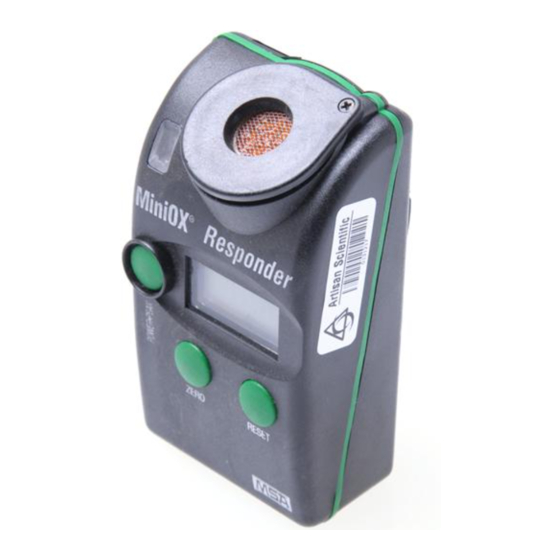
Section 3, MiniOX Responder Section 3 ® MiniOX Responder Oxygen Detector (P/Ns 710965 and 10008676) Instructions for Use and Maintenance " WARNINGS FAILURE TO FOLLOW CAN RESULT IN SERIOUS PERSONAL INJURY OR DEATH. 1. Alarm functions must be checked and a response check must be performed daily. -
Page 23: Cautions
Section 3, MiniOX Responder " CAUTIONS 1. To prevent sensor damage, store the instrument under the following conditions: OPTIMAL INTERMITTENT STORAGE TEMPERATURE TEMPERATURE C to 50 C to 32 (-20 F to 120 F to 90 2. Acid gases, such as CO , will shorten the life of the sensor. -
Page 24: Low Battery Alarm
Section 3, MiniOX Responder The low alarm, indicating oxygen deficiency, is high-rate intermittent and latching. This is indicated by an "A" on the display and a beep approximately every 1/2-second. It is not possible to mute the low alarm level while the deficiency persists. -
Page 25: Setting Alarm Setpoints
Section 3, MiniOX Responder appear on the display. The monitor then spans the instrument. When calibration is complete, the instrument beeps three times. Within the next five seconds, if you press and hold the Power Peak button for two seconds, you will be able to change the alarm settings. -
Page 26: Specifications
Section 3, MiniOX Responder Specifications 0-100% oxygen, RANGE over range indicated by - - - 30 seconds or less RESPONSE TIME to 90% of final reading TEMPERATURE RANGE C to 40 C (14 F to 104 (COMPENSATED) HUMIDITY 15 - 90% (non-condensing) 60 days with five minutes of alarm per day BATTERY LIFE... -
Page 27: Miniox ® Responder
Section 4, MiniOX Responder Remote Oxygen Detector Section 4 ® MiniOX Responder Remote Oxygen Detector (P/Ns 10001923 and 10008675) Instructions for Use and Maintenance " WARNINGS FAILURE TO FOLLOW CAN RESULT IN SERIOUS PERSONAL INJURY OR DEATH 1. Alarm functions must be checked and a response check must be performed daily. -
Page 28: Cautions
Section 4, MiniOX Responder Remote Oxygen Detector " CAUTIONS 1. To prevent sensor damage, store the instrument under the following conditions: OPTIMAL INTERMITTENT STORAGE TEMPERATURE TEMPERATURE C to 50 C to 32 (-20 F to 120 F to 90 2. Acid gases, such as CO , will shorten the life of the sensor Turning ON/OFF... -
Page 29: Low Battery Alarm
Section 4, MiniOX Responder Remote Oxygen Detector If a warning condition remains, the tone will only be temporarily silenced. The default setting for the "W" alarm is 22% O The low alarm, indicating oxygen deficiency, is high-rate intermittent and latching. This is indicated by an "A"... -
Page 30: Calibration Check
Section 4, MiniOX Responder Remote Oxygen Detector Calibration Check While the instrument is turned ON, press and hold both the Zero and Reset buttons; then, press the Power Peak button. The instrument beeps once and the descriptor "↑SET↓" appears on the display. The monitor then spans the instrument. -
Page 31: Replacing Sensor Assembly
Section 4, MiniOX Responder Remote Oxygen Detector Replacing Sensor Assembly Remove the remote oxygen sensor and cable assembly from the instrument by unscrewing the jack assembly counterclockwise and removing jack from the top of the sensor cap. Replace the new oxygen sensor and cable assembly by reversing the above procedure. -
Page 32: Chlorine Detector
Section 5, MiniCl Responder Section 5 MiniCl Responder Chlorine Detector (P/Ns 10020744 and 10020747) Instructions for Use and Maintenance " WARNINGS FAILURE TO FOLLOW CAN RESULT IN SERIOUS PERSONAL INJURY OR DEATH. 1. The MiniCl Responder is designed to measure Chlorine in air only. Do not use this monitor to sample for Cl in gases other than air. -
Page 33: Cautions
Section 5, MiniCl Responder " CAUTIONS 1. To prevent sensor damage, store the instrument under the following conditions: OPTIMAL INTERMITTENT STORAGE TEMPERATURE TEMPERATURE C to 50 C to 32 (-20 F to 120 F to 90 Turning ON/OFF When unit is delivered, the battery is not connected. -
Page 34: Low Battery Alarm
Section 5, MiniCl Responder To mute a Warning level, press the RESET button. This silences the audible tone, but the visual indicator remains. If a warning condition remains, the tone will only be temporarily silenced. It is not possible to mute the alarm level while it persists. The alarm level can only be reset once the concentration falls below the alarm level. -
Page 35: Setting Alarm Setpoints
Section 5, MiniCl Responder Connect the calibration cap to the sensor cap. Attach the calibration gas to the cal cap. Turn ON the gas. Wait for the display reading to stabilize; then, adjust the concentration on the display by pressing the ↓ (labeled Zero) or ↑ (labeled Reset) to read the same as the concentration of the cylinder of gas attached. -
Page 36: Replacing Sensor Assembly
Section 5, MiniCl Responder has been out of service or the battery has been out of the instrument for more than one day, it is recommended that the instrument not be used or zeroed for a period of 12 hours. This allows the sensor time to equilibrate. -
Page 37: Interferant Data
Section 5, MiniCl Responder Specifications DIMENSIONS 4-1/8"(L) x 2-1/4"(W) x 1-3/4" (H) WEIGHT 7 oz. +0.1 ppm Cl at constant temperature; at -10 C and 50 ACCURACY the reading shall not change by more than 0.2 ppm than at ambient temperatures dB LEVEL OF 93 dB at one foot typical ALARMS... -
Page 38: Replacement Parts
Section 5, MiniCl Responder Replacement Parts COMPONENT/ASSEMBLY PART NO. Sensor Assembly 10021355 9-V Battery 628817 Calibration Cap 10028451 Battery Cover Door with slotted 710493 screws Slotted Screwdriver 632655 Belt Clip 710489 Calibration Gas 710331 Calibration Regulator 465895 Calibration Tubing, 30-inch 485030 Special Instructions Due to the high reactivity of Chlorine gas,... -
Page 39: Miniclo 2 Tm Responder
Section 6, MiniClO Responder Section 6 MiniClO Responder Chlorine Dioxide Detector (P/Ns 10020745 and 10020749) Instructions for Use and Maintenance " WARNINGS FAILURE TO FOLLOW CAN RESULT IN SERIOUS PERSONAL INJURY OR DEATH. 1. The MiniClO Responder is designed to measure Chlorine Dioxide in air only. -
Page 40: Cautions
Section 6, MiniClO Responder " CAUTIONS 1. To prevent sensor damage, store the instrument under the following conditions: OPTIMAL INTERMITTENT STORAGE TEMPERATURE TEMPERATURE C to 50 C to 32 (-20 F to 120 F to 90 Turning ON/OFF When unit is delivered, the battery is not connected. -
Page 41: Low Battery Alarm
Section 6, MiniClO Responder To mute a Warning level, press the RESET button. This silences the audible tone, but the visual indicator remains. If a warning condition remains, the tone will only be temporarily silenced. It is not possible to mute the alarm level while it persists. The alarm level can only be reset once the concentration falls below the alarm level. -
Page 42: Setting Alarm Setpoints
Section 6, MiniClO Responder Connect the calibration cap to the sensor cap. Attach the calibration gas to the cal cap. Turn ON the gas. Wait for the display reading to stabilize; then, adjust the concentration on the display by pressing the ↓ (labeled Zero) or ↑ (labeled Reset) to read the same as the concentration of the cylinder of gas attached. -
Page 43: Installing/Replacing The Battery
Section 6, MiniClO Responder entered by the same method. After accepting the alarm level, the monitor returns to displaying the concentration reading. Installing/Replacing the Battery Remove belt clip by pressing the two tabs near the top and releasing from the back. Remove the two slotted head screws on the back of the case, located under the clip. -
Page 44: Specifications
Section 6, MiniClO Responder Specifications 0-6 ppm, RANGE over range indicated by - - - 90 seconds or less RESPONSE TIME to 90% of final reading C to 40 C (14 F to 104 TEMPERATURE C to 50 C if calibrated at RANGE temperature of use and recalibrated again if... -
Page 45: Interferant Data
Section 6, MiniClO Responder Interferant Data This data is presented as the indicated output in ppm, which would result from the application of 2 ppm of the test gas. CONCEN- READ- TEST GAS TRATION Methane (CH 1.50% Carbon monoxide (CO) 300 ppm Hydrogen Sulfide (H S) 10 ppm Sulfur Dioxide (SO... - Page 46 Section 6, MiniClO Responder 1. If condensation in the sample line is suspected, dry the sample line by drawing a sample with the sample line attached in a low humidity atmosphere. 2. To verify operation of a MiniClO Responder equipped with a Chlorine Dioxide sensor, perform response check with the sample line in place.
- Page 47 Section 7, Suggested Daily Use for All Units Section 7 Suggested Daily Use for All Units (MiniCO unit shown) Turn ON the MiniCO Responder. The instrument can be zeroed in fresh air by pressing the ZERO button while "zero" flashes on the display. Artisan Technology Group - Quality Instrumentation ...
- Page 48 Section 7, Suggested Daily Use for All Units Test the instrument’s response to gas: ® Bump check with Squirt Bump Test Gas OR (see step 4): OR: Test the instrument’s response to gas with a calibration gas cylinder. Artisan Technology Group - Quality Instrumentation ... Guaranteed | (888) 88-SOURCE | www.artisantg.com...
- Page 49 Section 7, Suggested Daily Use for All Units The instrument should read within the tolerance printed on the cylinder or can. If not, calibration is required. See "Calibration Check Adjustment." Artisan Technology Group - Quality Instrumentation ... Guaranteed | (888) 88-SOURCE | www.artisantg.com...
Need help?
Do you have a question about the MiniOX 710965 and is the answer not in the manual?
Questions and answers