Table of Contents

Related Manuals for Dräger MSI EM200plus


Summary of Contents for Dräger MSI EM200plus
- Page 1 Instruction manual MSI EM200plus + EM200plus-i Dräger MSI GmbH Rohrstraße 32 58093 Hagen Tel.: +49-2331 / 9584 - 0 Fax: +49-2331 / 9584 - 29 e-mail: info@draeger-msi.de 5695004 Edition 09 – October 2019 (Edition 01 – April 2011)
-
Page 2: Table Of Contents
3. Starting up and operation ....................6 3.1 Preparing for use ......................6 3.2 Push buttons ....................... 6 3.2.1 Switching on / off the MSI EM200plus ..............6 3.2.2 Functions of the push buttons ................7 3.3 Info screen and help function ..................7 3.4 Test of measuring gas duct .................. - Page 3 Instruction Manual Dräger MSI EM200plus + EM200plus-i 10.3.2 Start of leak measurement ................23 11. Special functions ......................24 11.1 Measuring combustion air temperature ..............24 11.2 Automatic switch off ....................24 11.3 Shelter of the CO sensor ..................25 11.3.1 Instruments without extension of CO measuring range ........
- Page 4 Instruction Manual Dräger MSI EM200plus + EM200plus-i 19.1 Storing ........................40 19.2 Maintenance ......................40 19.3 Service ........................40 19.4 Consumables and accessories ................40 20. China RoHS 2 ......................41...
-
Page 5: Reference Notes
The MSI EM200plus is unlicensed as a gas detection alarm or personal security equipment. Any use of the MSI EM200plus requires a full understanding and strict adherence to these instructions and to national and international standards. -
Page 6: The Instrument
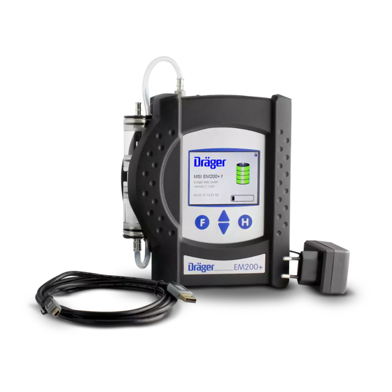
Instruction Manual Dräger MSI EM200plus + EM200plus-i 2. The instrument The MSI EM200plus is an electronic multiple channel measuring instrument, analysing the flue gas concentrations and combustion data for engineers, service, environmental protec- tion, etc.. All measurements and checks may be documented by printing or data storage. -
Page 7: Starting Up And Operation
Connect the gas conditioner with the gas inlet of the MSI EM200plus. Never forget to use the gas conditioner to protect the instrument, otherwise pump and sensors could be dam- aged. -
Page 8: Functions Of The Push Buttons
3.2.2 Functions of the push buttons The functions of the push buttons are always shown in the last row of the display. The MSI EM200plus is equipped with a touch screen. A contact at the display replaces the push button signal. -
Page 9: Test Of Measuring Gas Duct
Instruction Manual Dräger MSI EM200plus + EM200plus-i 3.4 Test of measuring gas duct Instruments with integrated gas duct control monitor the gas duct continuously. If the gas flow is too small an error message is generated and displayed. The tightness of the com- plete measuring gas duct may be proved by closing the gas inlet of the probe. -
Page 10: Selection Of Functions
Instruction Manual Dräger MSI EM200plus + EM200plus-i 4. Selection of functions Selectable functions are: Switch-off = Switches off the instrument Customer administration = Selection or input of customer data Visual examination = Documentation of visual examination Flue gas analysis = Select type of flue gas measurement... -
Page 11: Visual Examination
Instruction Manual Dräger MSI EM200plus + EM200plus-i With ( ) the marked customer number and if existing Edit customer data will be shown. With this data can be edited and with it will be (SELECT) (END) stored. With new customer data can be applied as follows:... -
Page 12: Flue Gas Measurement
Instruction Manual Dräger MSI EM200plus + EM200plus-i 7. Flue gas measurement 7.1 Select type of flue gas measurement Selectable functions are: Analysis / Stack losses = Flue gas analysis / Stack losses calculation Average = Average measurement CO measurement = CO measurement Comb. -
Page 13: Core Stream Detection
Instruction Manual Dräger MSI EM200plus + EM200plus-i 7.1.3 Core stream detection In the flue gas stream exist some regions, where only parts are filled with exhaust gas. Therefore it is importend to take the gas out of the core stream. The core stream is characterised by maximum temperature and minimum O2 concentration. -
Page 14: Input Of Soot Numbers
Instruction Manual Dräger MSI EM200plus + EM200plus-i 7.1.6 Input of soot numbers This function only appears in analysis and average measurement if input is activated. With the boiler soot numbers may be entered. (INPUT) If all inputs have been done, with... -
Page 15: Display Screen In Table Form
Instruction Manual Dräger MSI EM200plus + EM200plus-i The calculation of flue gas loss for condensing boilers can be activated. Is this function deactivated or is pushed, the (CONTINUE) display screen in table form is called. The used abbreviations for the measuring channels mean:... -
Page 16: Average Measurements
Instruction Manual Dräger MSI EM200plus + EM200plus-i 7.3 Average measurements In many cases average values are measured to get repeatable results at time varying com- bustions. For this a defined time for averaging is required. So at bigger combustions a half hour mean value is demanded, on the other hand for with solid fuels fired combustions the averaging for 15 minutes is required. -
Page 17: Result Of Average Measurement
Instruction Manual Dräger MSI EM200plus + EM200plus-i 7.3.2 Result of average measurement With ( ) the “documentation menu” is called. CONTINUE 7.4 CO measurement In some cases, requested by regional rules, the concentration of O , CO and CO undiluted in the stack gas is of interest. -
Page 18: Combustion Air O Measurement In Air Ducts
Instruction Manual Dräger MSI EM200plus + EM200plus-i 7.5 Combustion air O measurement in air ducts At room-air independent combustions the tightness of the combined combustion-air duct and flue exhaust system may be checked by measuring the O concentration in the air duct with a special multi hole probe. -
Page 19: Pressure Measurements
Instruction Manual Dräger MSI EM200plus + EM200plus-i Fresh air should be sucked in and no tube should be connected to the pressure inlets. With all zero points will be recalibrated. (START) 8. Pressure measurements Selectable pressure measurements are: Medium press. -
Page 20: Micro Pressure Measurement
The measurement of the stack gas temperature is done with a gas probe with integrated thermocouple. Connect the plug of the thermocouple with the bushing (marked TG) of the MSI EM200plus-i and insert the probe into the stack. With the displayed stack temperature is accepted. -
Page 21: Start Of Flow Measurement
In some countries (e.g. Spain) exists a regulation, to measure ambient air CO at the site of a combustion to prove their tightness. For this the MSI EM200plus needs no external sensor. At a place with fresh air, without CO content, the value has to be 0 ppm. -
Page 22: Gas Pipe Checks
Instruction Manual Dräger MSI EM200plus + EM200plus-i With the result of the ambient air CO (CONTINUE) measurement is displayed. With ( ) the “documentation menu” is called. CONTINUE 10. Gas pipe checks 10.1 Selection of gas pipe checks Selectable functions are:... -
Page 23: Leak Rate Measurement (Dvgw Trgi 2008)
(CONTINUE) 10.3 Leak rate measurement (DVGW TRGI 2008) With the MSI EM200plus it is possible to realize a leak rate measurement for gas pipe with 23, 50 respectively 100 mbar operational pressure. Are all installed consumers disconnected from the gas pipe by closed valves, the pressure has to be increased to 50, 55 respectively 110 mbar. -
Page 24: Evaluation Of Gas Pipe Volume
Instruction Manual Dräger MSI EM200plus + EM200plus-i 10.3.1 Evaluation of gas pipe volume Is the volume of the gas pipe known, change to “Frac volume” with . Put in the first fraction of volume. Adopt it (CONTINUE) with and put in the next fraction. -
Page 25: Special Functions
11. Special functions 11.1 Measuring combustion air temperature The MSI EM200plus is equipped with a built-in temperature sensor, which is able to measure in first approximation the temperature of the ambient (room temperature) and where appli- cable the temperature of the combustion air. -
Page 26: Shelter Of The Co Sensor
Instruction Manual Dräger MSI EM200plus + EM200plus-i 11.3 Shelter of the CO sensor The instrument is equipped with a special function protecting the sensors from getting harmed by too high CO concentrations. Already during the first contact with the flue gas the instrument realises how fast the con- centration rises and recognises if the measuring range (8,000 ppm) will be exceeded. -
Page 27: Documentation Menu
Instruction Manual Dräger MSI EM200plus + EM200plus-i 12. Documentation menu Selectable functions are: Back = Calls the last display screen of actual measurement New Measurement = Start of a new measurement of the same type End, release = End of measurement, the results are released... -
Page 28: Data Menu
Instruction Manual Dräger MSI EM200plus + EM200plus-i 13.2 Data menu Selectable functions are: Info = info function of the data menu Show: last = shows last stored data record Show: first = shows first stored data record Clear data table = deletes all stored data records... -
Page 29: Clear Data Table
Instruction Manual Dräger MSI EM200plus + EM200plus-i Following types of measurement may be shown: Flue gas = flue gas analysis / stack losses / average values = CO measurement Comb. O = combustion air O concentration in air ducts Pr.mbar = pressure measurements in the range up to 100 mbar Pr.Pa... -
Page 30: Info Function
Instruction Manual Dräger MSI EM200plus + EM200plus-i 14. Info function The instrument informs about the analyser (MSI EM200+), the manufacturer (Dräger MSI GmbH), the version of the firmware (e.g. 2.1.020) the serial number of the analyser, the date of the next service and actual date and time. -
Page 31: Nox Factor (Only For Instruments With Option No Sensor)
Instruction Manual Dräger MSI EM200plus + EM200plus-i 15.2 NOx factor (only for instruments with option NO sensor) This function calculates NOx, if the part of NO from NO is known. Is e.g. from a measurement known, that the NO part is 5 % from the NO concentration, the NO measurement value has to be multiplied with 1.05, to get NOx. -
Page 32: Average Time
Instruction Manual Dräger MSI EM200plus + EM200plus-i 15.6 Average time 30 s = 30 seconds average time 60 s = 1 minute average time 15 min = average time needed for solid fuel combustions 30 min = 1/2 hour average time 15.7 Draft... -
Page 33: Measurement Factory Settings
Instruction Manual Dräger MSI EM200plus + EM200plus-i 15.9 Measurement factory settings With this function all modified measurement settings may be cancelled and the factory settings may be restored. 16. Device settings Selectable functions are: Clock = adjust date and time... -
Page 34: Delete Single Measurement
Instruction Manual Dräger MSI EM200plus + EM200plus-i 16.2 Delete single measurement This function may allow deleting a single data record. 16.3 Backlight Selectable intensity levels are: 25 %, 50 %, 75 % und 100 %. The selected intensity level remains held even after switch off. -
Page 35: Printer
Instruction Manual Dräger MSI EM200plus + EM200plus-i 16.6 Printer Printer MSI IR3: Data transfer and printing is much quicker than with HP compatible printers. Printer HP: Data transfer is conforming to the HP protocol and fits to all HP compatible printers, of course for MSI IR3 too. -
Page 36: Instrument Factory Settings
Instruction Manual Dräger MSI EM200plus + EM200plus-i 16.9 Instrument factory settings The function “Only user adjustments” cancels all modified settings and restores the factory settings. The function “All configurations” does this too and restores additionally all configurations which are made with the PC-software, e.g. -
Page 37: Error Messages
Instruction Manual Dräger MSI EM200plus + EM200plus-i 17.2 Error messages Error message Error cause Remedy O2 sensor probe has been in flue calibrate again with fresh air sensor defect service CO sensor probe has been in flue calibrate again with fresh air... -
Page 38: Operation References
Instruction Manual Dräger MSI EM200plus + EM200plus-i 17.3 Operation references 17.3.1 Operation references - symbols On the display symbols may indicate following activated functions: Symbol 1 charge of battery Symbol 2 battery is charging Symbol 3 error Symbol 4 internal pump is working... -
Page 39: Technical Data
Instruction Manual Dräger MSI EM200plus + EM200plus-i 18. Technical data 18.1 General technical data general technical data humidity 10 - 90 % RH not condensing barometric pressure 800 … 1,100 hPa operating temperature +5 °C ... + 40 °C storage temperature -20 °C ... -
Page 40: Technical Data Of Measured And Calculated Values
Instruction Manual Dräger MSI EM200plus + EM200plus-i 18.2 Technical data of measured and calculated values Measure- Principle Range Resolution Accuracy 1 °C temperature -10...+100 °C 0.1 °C combustion air temperature thermocouple -10...1000 °C 0.1 °C < ± 2 °C or flue gas <... -
Page 41: Maintenance And Service
Instruction Manual Dräger MSI EM200plus + EM200plus-i 19. Maintenance and service 19.1 Storing El.-chem. gas sensors react to gases in the ambient, even if the instrument is switched off. Make sure, that the instrument is stored in a place with room temperature without contami- nation with solvents, exhaust gases or combustibles and that it becomes recharged period- ically. - Page 42 Instruction Manual Dräger MSI EM200plus + EM200plus-i 20. China RoHS 2 Hazardous Substances Lead Mercury Cadmium Hexavalent Polybromin- Polybromin- Part Name (Pb) (Hg) (Cd) Chromium ated biphenyls ated diphenyl (Cr(VI)) (PBB) ethers (PBDE) O2 sensor PCBA main PCBA display Brass parts This table is prepared in accordance with the Provisions of SJ/T 11364.
Need help?
Do you have a question about the MSI EM200plus and is the answer not in the manual?
Questions and answers