Dräger VarioGard Instructions For Use Manual
Gas warning system
Hide thumbs
Also See for VarioGard:
- Installation instructions (4 pages) ,
- Instructions for use manual (280 pages)

Subscribe to Our Youtube Channel
Related Manuals for Dräger VarioGard


Summary of Contents for Dräger VarioGard
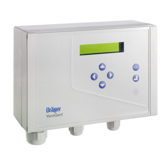
- Page 1 VarioGard Gas warning system Instructions for Use VarioGard VarioGard VarioGard VarioGard Software 2.nn...
-
Page 2: Table Of Contents
Mechanical installation ................48 Electrical installation ................. 50 Wiring arrangement ................51 Installation layouts ................52 Connection assignment ..............53 Starting up the VarioGard system ............56 For the user: Operation ....................57 Factory basic settings ................58 Troubleshooting ..................61 Maintenance ................... -
Page 3: For Your Safety
The VarioGard System is only to be used for purposes specified here. Maintenance Repair of the VarioGard System may only be carried out by trained service personnel. Only authentic Dräger spare parts may be used for maintenance. -
Page 4: Intended Use
– for controlling connected components such as warning transparencies, signal sirens, fans etc. – for installation in control cabinets: with an installation kit for wall mounting. – for operation as a gas alarm with a VarioGard gas sensor and additional power supply. -
Page 5: Performance Test
– for installation in control cabinets; with an installation kit for wall-mounting. Must not be used in explosion-hazard areas None of the components of the VarioGard system are approved for use in areas with explosion hazard. Performance test A VarioGard central unit, together with the CO transmitter, successfully underwent a qualification test according to VDI 2053, conducted by the Rhineland Technical Inspectorate (Inspectorate job no. -
Page 6: Installing The Variogard System
Installing the VarioGard system Mechanical installation Installing the VarioGard system The VarioGard system may only be installed by duly trained specialist personnel. Mechanical installation VarioGard central unit Position the central unit in a clearly visibly, easily accessible place. 1 Remove strips from upper part (not fitted before delivery). - Page 7 Installing the VarioGard system Mechanical installation 1 Remove strips from upper part (not fitted before delivery). 2 Undo the four screws on the upper part and remove the upper part (not fitted before delivery). 3 Fit second cable entry (optional accessory) if the cable is to continue to another transmitter.
-
Page 8: Electrical Installation
Installing the VarioGard system Electrical installation Electrical installation – The VarioGard system wiring may only be routed and connected by an electrician in accordance with the relevant regulations. – Shielded cables are not required. Only a limited number of system components such as transmitters can be connected to a single central unit. -
Page 9: Wiring Arrangement
Installing the VarioGard system Electrical installation Wiring arrangement VarioGard VarioGard VarioGard VarioGard VarioGard The maximum length of the system bus cable is determined by the total length of the slave cables, e.g. L1 + L2 + L3 + L4 + L5. -
Page 10: Installation Layouts
Warning panel 24 V Mains Central Relay with battery for 1 hour unit 115 / 230 V Battery module 28 V VarioGard Relay Module and VarioGard Converter Module Installation according the installation instructions 90 23 577 or 90 23 578. -
Page 11: Connection Assignment
Central unit: Connection 1 Power (terminal contacts) 230 V, 50 to 60 Hz, max. 300 mA, max. 55 VA Pin assignment: L (Outer conductor, VarioGard power feeder) ➀ ➂ ➁ (Phase conductor output, with 4 A slow-blow fuse) N (Neutral conductor) - Page 12 Installing the VarioGard system Electrical installation – Relay switching contacts supplied with externally fused supply. ➀ ➂ ➁ ➀ ➂ ➁ ➀ ➂ ➁ ➀ ➂ ➁ ➀ ➂ ➁ ➀ ➂ ➁ 1 System bus (terminal contacts) 30 V nominal DC output, max. 1.2 A current-load as a slave supply...
- Page 13 Installing the VarioGard system Electrical installation 1 Emergency power supply (terminal contacts) – Installation layout for car parks on page 52. 28 V nominal DC, constant-voltage input Pin assignment: + (voltage input) K (battery voltage monitor) GND (ground) Transmitter: Plug-in connection in upper part...
-
Page 14: Starting Up The Variogard System
Starting up the VarioGard system Starting up the VarioGard system The VarioGard transmitters connected to the system bus are precalibrated before delivery and immediately ready for use after the DrägerSensor warm-up time. Connect the system to the power supply. – Display on central unit: Dräger VarioGard... -
Page 15: Operation
The gas inlet to the transmitters must not be obstructed in order to ensure accurate measurement. Gas concentration display in normal mode Dräger VarioGard Display on central unit: LED shows steady green light Transmitter... -
Page 16: Factory Basic Settings
Operation Factory default settings Factory default settings On being started up for the first time, the system operates with the basic factory settings: – The emergency power supply connection and the alkaline batteries of the central unit are not monitored. –... - Page 17 Alarms A1, A2 and A3 are not self-locking and cannot be acknowledged. 1 The LED on the central unit and on the transmitter concerned flashes according to the particular alarm; see table. VarioGard VarioGard Display on central unit e.g.: Transmitter...
- Page 18 Transmitter Comms. interrupted ! Display on central unit in case of a fault, e.g.: Dräger VarioGard See page 61 for warning and fault messages and troubleshooting. Error EEPROM ! The alarm relays are switched according to the particular alarm; see table.
-
Page 19: Troubleshooting
Troubleshooting Troubleshooting Error message or warning Cause Remedy Electronic fault Call DrägerService. Dräger VarioGard Error FLASH ! Electronic fault Call DrägerService. Dräger VarioGard Error EEPROM ! Electronic fault Call DrägerService. Dräger VarioGard Error RAM I2C ! Clock setting lost due to voltage loss Set clock, see page 70. - Page 20 DrägerService. Mainten. necessary ! properly Central unit not connected to Check installation and correct. Dräger VarioGard mains Emerg. power supply ! Voltage loss Correct voltage loss. If the remedies indicated do not solve the problem, please call DrägerService.
-
Page 21: Maintenance
Maintenance intervals Visual inspection At least every 3 months to determine operational readiness. Inspect the complete VarioGard system for damage and check that gas access to the transmitters is unobstructed. Routine inspections As required by local regulations (in Germany, VDI 2053 - Ventilation and air conditioning systems for car parks and tunnels / car parks, State car parks ordinance, etc.). -
Page 22: Changing Transmitter
Maintenance Changing transmitter Changing transmitter One transmitter or a succession of transmitters can be replaced by new ones at the end of their operating time without interrupting operation. Transmitters or transmitter upper parts must only be replaced by identical new ones (i.e. with the same part number). Always use brand-new transmitters or Repair / Replacement Exchange Parts (REX), see page 81. -
Page 23: Replacing The Battery In The Central Unit
1) in the case of an interruption to the supply voltage. In Germany this is a requirement of VDI 2053 for underground car parks. 2 Remove strips from upper part of VarioGard central unit. 3 Undo the four screws on the upper part and remove upper part. -
Page 24: Menu Mode
Menu mode Menu structure Menu mode The menu mode is operated by means of 6 keys: 4 cursor keys [ q, l, k, j ], an Escape key [ ESC ] and an Enter key [ ], and the display on the central unit. [ q ], [ l ] key Change menu options / functions Change symbols / figures at the cursor position... -
Page 25: Entering The Password
If the passwords preset before delivery have been changed with the function "Change passwords" – page 76 – and then forgotten: Call DrägerService. Entering the password In measurement mode, display on central unit: Dräger VarioGard Press [ ] key to change over to input password mode: Password ? Enter password: Use [ q ] and [ l ] keys to set number or letter. -
Page 26: Setting The Language
Menu mode Setting the language Displaying peak values Setting the language In measurement mode: Press [ ] key. Enter password (for maintenance or configuration). Press [ ] key to change over to menu mode. MENU: Display: MEASUREMENT Use [ q ] or [ l ] key to select the » SET LANGUAGE « option. MENU: SET LANGUAGE Press [... -
Page 27: Clearing Peak Values
Menu mode Clearing peak values Displaying alarms Clearing peak values In measurement mode: Press [ ] key. Enter password (for maintenance or configuration). Press [ ] key to change over to menu mode. MENU: Display: MEASUREMENT Use [ q ] or [ l ] key to select the » CLEAR PEAK VALUES « option. MENU: CLEAR PEAK VALUES Press [... -
Page 28: Setting The Clock
Menu mode Setting the clock Setting the clock The clock only needs to be set if a mode with exposure evaluation has been selected. In measurement mode: Press [ ] key. MENU: Enter password (for maintenance or configuration). MEASUREMENT Press [ ] key to change over to menu mode. -
Page 29: Displaying Number Of Exposure
Menu mode Displaying number of exposure Registering all slaves Displaying number of exposure (only when using transmitters with activated exposure evaluation) In measurement mode: Press [ ] key. Enter password (for maintenance or configuration). Press [ ] key to change over to menu mode. Display: MENU: MEASUREMENT Use [ q ] or [ l ] key to select the »... -
Page 30: Changing Transmitter Upper Part
Menu mode Registering all slaves Changing transmitter upper part – Once all the slaves have been registered, the display reads e.g.: Register slave ? 8 Slave registered ! Press [ ] key to process the registration data in the central unit. During Register slave ? this time, display: Wait . - Page 31 Menu mode Changing transmitter upper parts Remove slave from the system bus – Connect slave ! Display then reads: 0 Slaves changed ! Connect slave ! Line disconnected ! New slave detected ! Connect new slave – Display: 1 Slaves changed ! Change other slaves in the same way.
-
Page 32: Testing Relays
Menu mode Testing the relays Testing the relays This function can be used to simulate the switching of the relays in the central unit and relay modules connected to the system bus. This function serves for checking the accessory connected to the relays. In measurement mode: Press [ ] key. -
Page 33: Deactivating Transmitters
Menu mode Deactivating transmitters Deactivating transmitters This function is used to disable a transmitter. When a transmitter is disabled, all the alarms and faults are suppressed. In Transmitter measurement mode the measured value for that transmitter is replaced by the disabled word »... -
Page 34: Changing The Password
Menu mode Changing passwords Changing passwords The passwords set before delivery i.e. 1 for maintenance and 2 for configuration can be changed by means of the » PASSWORD MAINTAIN « or » PASSWORD CONFIG. « functions. In measurement mode: Press [ ] key. -
Page 35: Displaying The Voltage
Menu mode Displaying the voltage Displaying the voltage This function can be used to query the supply voltage of the individual slaves in order to check the wiring. In measurement mode: Press [ ] key. Enter password (for maintenance or configuration). MENU: Press [ ] key to change over to menu mode. -
Page 36: Technical Data
Type of protection of housing IP 54, EN 60 529 Performance test A VarioGard central unit, together with the CO transmitter, successfully underwent a qualification test according to VDI 2053, conducted by the Rhineland Technical Inspectorate (Inspectorate job no. 432-989713) in 1999. - Page 37 Approx. 7 kg (with lead storage batteries) Dimensions with cable inlet 190 mm x 245 mm x 125 mm (H x W x D) VarioGard Relay Module see installation instructions 90 23 577 VarioGard Converter Module see installation instructions 90 23 578...
-
Page 38: Measurement Principle Of Transmitter
Measurement principle of transmitter Measurement principle of transmitter CO, NO, NO and NH transmitter The VarioGard CO, NO, NO and NH transmitters are electrochemical measuring transducers for measuring the partial pressure of the respective gas under atmospheric conditions. measured gas... -
Page 39: Order List
Order list Order List Designation and description Order No. VarioGard central unit Model D, 230 V for wall mounting 83 15 150 for installation in switch cabinet 83 15 160 Model Export, 230 V for wall mounting 83 15 350... -
Page 40: Index
Index Index larm thresholds ..................58 Ambient conditions .................. 78 attery module, connection assignment ..........55 Battery module, intended use ..............46 Battery module, mechanical installation ............ 49 Battery module, Technical Data ............... 79 Battery module, wiring arrangement ............51 Busloads .................... - Page 41 Index lectrical installation ................50 Emergency power supply, installation layout ..........52 Enter key ....................66 Entering the password ................67 Error messages ................. 61, 62 Escape key ....................66 Explosion-hazard areas ..............45, 47 actory default settings ................58 Faults ....................
- Page 42 Index transmitter, measuring principle ............80 Operation ....................57 Order List ....................81 Performance test ..................47 egistering all slaves ................71 Remote acknowledge, installation layout ..........54 Repair and replacement parts ............64, 81 Replacing the battery in central unit ............65 Routine inspection ...................
-
Page 43: Drilling Templates
Bohrschablonen / Drilling template Zentralgerät / Central unit – Akkumodul / Battery module 146 mm (5.75") -
Page 45: Transmitter
Bohrschablonen / Drilling template Messfühler / Transmitter 106 mm (4.17") - Page 46 Dräger Safety AG & Co. KGaA Revalstraße 1 D-23560 Lübeck Germany Tel. +49 451 8 82 - 27 94 +49 451 8 82 - 49 91 www.draeger-safety.de www.draeger-safety.com 90 23 572 - GA 4679.200 en © Dräger Safety AG & Co. KGaA edition - August 2005 Subject to alteration...
Need help?
Do you have a question about the VarioGard and is the answer not in the manual?
Questions and answers