
Subscribe to Our Youtube Channel
Related Manuals for Seametrics EX80 Series


Summary of Contents for Seametrics EX80 Series
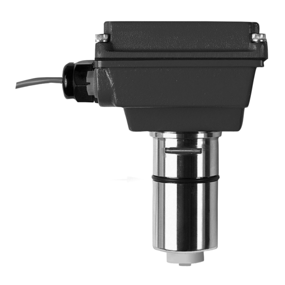
- Page 1 EX80 Series ELECTROMAGNETIC FLOW SENSOR INSTRUCTIONS EX81 EX82 The Leader in Flow Meter Value.
-
Page 2: Table Of Contents
TABLE OF CONTENTS General Information Modularity, Output, Inser tion Depth, Fittings, Par ts Diagram ........Page 1 Installation Distor ted Flows, Fitting Installation, Meter Installation, Positioning the Meter ....Page 2 Straight Pipe Recommendations ..................Page 3 Correct and Incorrect Installations .................. Page 4 Electrical Connections General Electrical Guidelines, Power, Pulse Output, Direction Indicator, Grounding Guidelines, Grounding Diagram .............. -
Page 3: General Information
See the section on “Connecting to PLC’s and other Controllers” before connecting to a non-SeaMetrics control. EX80 PARTS DIAGRAM Cover or Module... -
Page 4: Installation
EX80 Series PVC meter tees are supplied with some up- Caution: Never remove the u-clip stream straight pipe. The length provided may be less retainer when the pipe is under pressure. -
Page 5: Straight Pipe Recommendations
INSTALLATION STRAIGHT PIPE RECOMMENDATIONS (x = diameter) Reduced Pipe Two Elbows In Plane Two Elbows, Out Of Plane Expanded Pipe Spiral Flow Propellor Meter Swirling Flow Partially Open Butterfly Valve Page 3... -
Page 6: Correct And Incorrect Installations
INSTALLATION CORRECT AND INCORRECT INSTALLATIONS INCORRECT CORRECT Ensures full pipe Allows air pockets to form at sensor INCORRECT CORRECT Post-valve cavitation can create air pocket Keeps pipe full at sensor CORRECT INCORRECT Air can be trapped Allows air to bleed off Caution: These flow sensors are not recommended for installation down- stream of the boiler feedwater pump where installation fault may expose the flow sensor to boiler pressure and temperature. -
Page 7: Electrical Connections
ELECTRICAL CONNECTIONS General Electrical Guidelines: Grounding Guidelines: • Whenever possible avoid running control cables • For best results, use a good quality earth ground, in the same conduit with AC power. Use shielded such as metallic water piping, or a stake driven control cable where this type of installation is into the ground. -
Page 8: Counter Or Plc, A055 4-20 Ma Output, Ft520 Controller
CONNECTIONS DIAGRAMS COUNTER OR PLC 11 - 24 Vdc 250 mA max. Power Input 11 - 24 Vdc 5 mA max. Pulse Output Frequency Input 25 hz per ft/sec 11 - 24 Vdc/Vac 100 mA max. Direction Output Direction Input EX SERIES COUNTER OR PLC DIGITAL INPUT... -
Page 9: Ft420 Display And Propor Tional Feed, Ft420 & 4-20 Ma Output, Fs30 Flow Switch
CONNECTIONS DIAGRAMS FT420 DISPLAY AND PROPORTIONAL FEED FT420 24 Vdc Power Sensor Pulse Input Scaled Power Input Proportional Feed Metering Pulse Output Pump Direction Output Pulse Pass-Thru EX SERIES Power 4-20mA FT420 DISPLAY AND 4-20 mA OUTPUT FT420 24 Vdc Power Sensor Pulse Input... -
Page 10: Zero Adjustment, Minimum Flow, Flow Range Diagram, Filtering, Electrode Coating, K-Factor, Location Of K-Factor Diagram
When the EX81 or 82 is powered up and there is no flow, K-factor. If the EX80 Series meter is ordered with its there should be no output pulses (or, if connected to the fitting, it is factory calibrated in the fitting. A K-factor (meter FT420, flow rate should read “0”). -
Page 11: Problems, Possible Causes, Things To Tr Y
TROUBLESHOOTING Problem Probable Cause Try... No pulse output Check Plumbing Pipe not full Connect to earth ground Unit not grounded Check for proper electrical wiring Excessive electrical noise Check for power across power No power input terminals Reverse connections Power Reversed Change output connections Output connections reversed Fluid conductivity <20 microseimans/cm... - Page 12 19026 72ND AVE SOUTH, KENT, WA 98032 USA (P) 253.872.0284 (F) 253.872.0285 LT-11792-B WWW.SEAMETRICS.COM 1.800.975.8153 03/09/04...
Need help?
Do you have a question about the EX80 Series and is the answer not in the manual?
Questions and answers