
Subscribe to Our Youtube Channel
Related Manuals for Seametrics EX80 Series


Summary of Contents for Seametrics EX80 Series
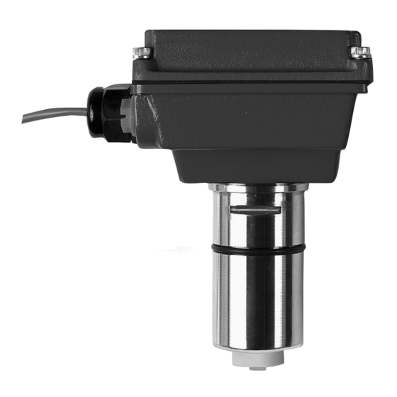
- Page 1 EX80 Series ElEctromagnEtic FloW SEnSor inStructionS EX81 EX82 The Leader in Flow Meter Value.
-
Page 2: Table Of Contents
tablE oF contEntS general information Modularity, Output, Inser tion Depth, Fittings, Par ts Diagram ........Page 1 installation Distor ted Flows, Fitting Installation, Meter Installation, Positioning the Meter ....Page 2 Straight Pipe Recommendations ..................Page 3 Full Pipe Recommendations .................. Page 4 Electrical connections General Electrical Guidelines, Power, Forward Flow Output, Reverse Flow Output, Grounding Guidelines, Grounding Diagram .............. -
Page 3: General Information
See the section on “Connecting to PLC’s and other Controllers” before connecting to a non-SeaMetrics control. EX80 PartS Diagram Cover or Module... -
Page 4: Distor Ted Flows, Fitting Installation, Meter Installation, Positioning The Meter
EX80 Series PVC meter tees are supplied with some upstream straight pipe. The length provided may be less caution: Never remove the u-clip than ten diameters upstream and five downstream. -
Page 5: Straight Pipe Recommendations
inStallation StraigHt PiPE rEcommEnDationS (X = diameter) reduced Pipe two Elbows in Plane two Elbows, out of Plane Expanded Pipe Spiral Flow Propeller meter Swirling Flow Partially open butterfly Valve Page 3... -
Page 6: Full Pipe Recommendations
inStallation Full PiPE rEcommEnDationS not rEcommEnDED rEcommEnDED Ensures full pipe Allows air pockets to form at sensor not rEcommEnDED rEcommEnDED Post-valve cavitation can create air pocket Keeps pipe full at sensor not rEcommEnDED rEcommEnDED Air can be trapped Allows air to bleed off caution: These flow sensors are not recommended for installation down- stream of the boiler feedwater pump where installation fault may expose the flow sensor to boiler pressure and temperature. -
Page 7: Electrical Connections
ElEctrical connEctionS general Electrical guidelines: reverse Flow output: Reverse flow output is available as an option. This open-collector isolated output does not • Whenever possible avoid running control cables in supply power. It functions like a polarity-sensitive switch the same conduit with AC power. closure. -
Page 8: Counter Or Plc, A055 4-20 Ma Output, Ft520 Controller
connEctionS DiagramS countEr or Plc 12 - 24 Vdc Power countEr or Plc Max. 6 mA, 30 Vdc Digital inPut Forward Output Max. 6 mA 30 Vdc Reverse Output (Option-15 only) EX SERIES *See Dual FT420 Diagram for an example of bidirectional connections. a055 4-20 ma outPut EX SERIES 24 Vdc Power... -
Page 9: Ft420 Display And Propor Tional Feed, Ft420 & 4-20 Ma Output, Fs30 Flow Switch
connEctionS DiagramS Ft420 DiSPlay anD ProPortional FEED FT420 24 Vdc Power Sensor Pulse Input Scaled Power Proportional Feed Metering Forward Output Pump Reverse Output (Option-15 only) Pulse Pass-Thru EX SERIES Power *See Dual FT420 Diagram for an 4-20mA example of bidirectional connections. Ft420 DiSPlay anD 4-20 ma outPut FT420 24 Vdc Power... -
Page 10: Dl75, Ft420/Dl75, Dual Ft420 Displays (Example Of Bidirectional Connection)
connEctionS DiagramS Dl75 Data loggEr Dl75 Sensor input Power Forward output reverse output (option-15 only) EX SEriES *See Dual Ft420 Diagram for an example of bidirectional connections. Ft420/Dl75 24 Vdc Power Ft420 Dl75 Pulse Sensor Power Scaled input Sensor input Forward output reverse output (option-15 only) -
Page 11: Zero Adjustment, Minimum Flow, Flow Rate Table, Presence Of Flow Indication, Filtering, Electrode Coating, Calibration ("K-Factor"), K-Factor Chart
As with any other flow sensor, there is a rate below which the EX80-series sensor cannot read. Check the If the EX80 Series meter is ordered with a saddle or wel- flow rate table below for the minimum flow rate detectable dolet fitting, find your K-factor in the chart below. - Page 12 Check for full pipe or install meter in the Empty pipe vertical position Not enough straight pipe Check for ten diameters upstream AND five diameters downstream 19026 72nD aVE SoutH, KEnt, Wa 98032 uSa (P) 253.872.0284 (F) 253.872.0285 LT-11792-F www.seametrics.com 1.800.975.8153 06/28/05...
Need help?
Do you have a question about the EX80 Series and is the answer not in the manual?
Questions and answers