Table of Contents
Advertisement
Quick Links
Advertisement
Table of Contents

Related Manuals for Seametrics Multi-Parameter Smart Sensor


Summary of Contents for Seametrics Multi-Parameter Smart Sensor
- Page 1 Multi-Parameter Smart Sensor and Datalogger PROUDLY MADE IN THE 9001...
-
Page 2: Table Of Contents
MULTI - PARAMETER INSTR TABLE OF CONTENTS Introduction ......................4 What is the Multi-Parameter Smart Sensor? .................4 Features ...............................4 Initial Inspection and Handling ......................4 Do’s and Don’ts ............................5 Installation and Operation ..................5 Connecting to External Power and a Computer ................5 Installing the Aqua4Plus Software ..............5 Calibration ......................6... - Page 3 MULTI - PARAMETER INSTR About this Manual This manual covers basic use of the Multi-Parameter Smart Sensor. Further details about each connected probe, including calibration information, can be found in their respective manuals. Be sure to refer to these manuals for important information on care and maintenance of your probe.
-
Page 4: Introduction
Parameter Sensor can measure pH, ORP, temperature, conductivity, salinity, TDS, pressure, level, and dissolved oxygen or turbidity, depending on configuration. The Multi-Parameter Smart Sensor is powered from a 12 VDC power supply and can be networked with other Seametrics Smart Sensors, either directly from a single computer or via a third party System. -
Page 5: Installation And Operation
(Note: the individual probe units do not have internal batteries.) Connect the Seametrics USB communication cable to the male connector on the power box. (For alternate connection options, see Appendix B.) Aux. -
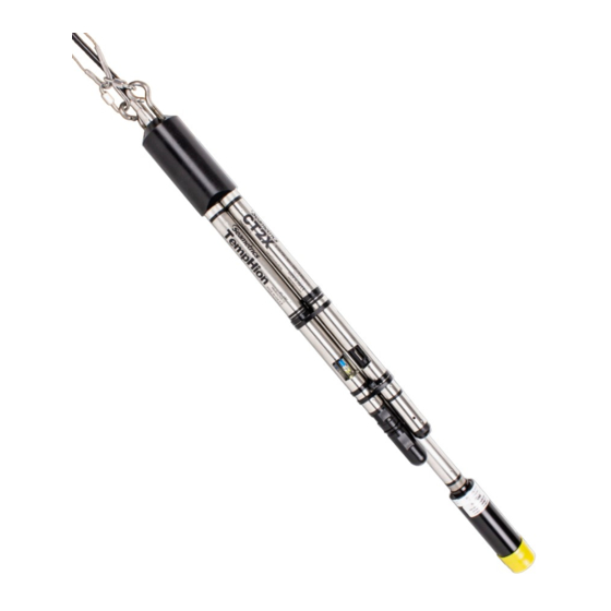
Page 6: Calibration
The black reference reservoir at the lower end of the TempHion Smart Sensor is shipped filled with Seametrics reference solution. (If your reference reservoir is not filled, see the Maintenance section of the TempHion manual.) The black reference assembly has two grooves. The upper groove contains a small hole that forms the liquid junction port. -
Page 7: Real-Time Data
To save this data to the Reports section click the button located next to the Single button in the Real-Time tab. This will permanently save this real-time data set to your Reports database. Seametrics • 253.872.0284 Page 7 seametrics.com... -
Page 8: Data Logging
Here you will name your data file and set up the recording interval and duration of each logging phase. Select your desired recording interval and duration for each phase, Aqua4Plus 2.0 will display the available memory at the bottom of the window. Seametrics • 253.872.0284 Page 8 seametrics.com... -
Page 9: Reports
Click on a report to bring up the report details. Reports are displayed in graphing view by default. You can zoom to specific sections by selecting a section with you mouse or by adjusting the slider below the graph. Seametrics • 253.872.0284 Page 9 seametrics.com... - Page 10 You may change the display units within the graph view by selecting the appropriate channel here: Click to switch to full screen graphing view Graph saving and export options are available here: Click to view data as a table Click to view data statistics Seametrics • 253.872.0284 Page 10 seametrics.com...
- Page 11 When using pH, ppm, or mVH units, all readings are automatically compensated for temperature and all field calibration factors are applied. When using millivolts or ohms, only the actual millivolt or resistance values are displayed - no adjustments are made. Seametrics • 253.872.0284 Page 11 seametrics.com...
-
Page 12: Storing Sensor
Connector White 12 VDC+ (Vaux) Purple Modbus D- (Not used) SDI-12 with — Yellow Modbus D+ (Not used) without connector Brown SDI-12 Signal Blue 12 VDC – (Gnd) Shield (may be green) Earth ground Seametrics • 253.872.0284 Page 12 seametrics.com... -
Page 13: Dimensions And Specifications
SDI-12 Output Serial Internal Math 32-bit floating point Operating Temperature Range -5° C to 40° C Storage Temperature Range -20° C to 80° C POWER External Supply 12 VDC – Nominal 9V-15VDC @ 15mA Seametrics • 253.872.0284 Page 13 seametrics.com... - Page 14 ± 0.5° C 0–5 ppm 0.01 ppm below 1% of reading or 0.02 0.1 above 4.0 whichever is greater Turbidity 0–400 NTU ± 2% or ± 2 NTU @ 0–3000 NTU 25° C whichever is greater Seametrics • 253.872.0284 Page 14 seametrics.com...
-
Page 15: Appendix B: Reading The Multi-Parameter Via Direct Read
READING THE MULTI - PARAMETER MULTI - PARAMETER INSTR Appendix B: Reading the Multi-Parameter via Direct Read While the Multi-Parameter sensor comes with Seametrics’ easy to use Aqua4Plus software, you can also use standard Modbus RTU or SDI-12 equipment to easily take readings, so ®... -
Page 16: Limited Warranty/Disclaimer
This limited warranty gives you specific legal rights; however, you may also have other rights which may vary from state to state. Seametrics • 19026 72nd Avenue South • Kent, Washington 98032 • USA (P) 253.872.0284 • (F) 253.872.0285 • 1.800.975.8153 • seametrics.com...
Need help?
Do you have a question about the Multi-Parameter Smart Sensor and is the answer not in the manual?
Questions and answers