Table of Contents
Advertisement
Quick Links
Advertisement
Table of Contents
Troubleshooting

Related Manuals for Siemens RVW26.000B27


Summary of Contents for Siemens RVW26.000B27
- Page 1 RVW26.000B27 Electronic Air / Fuel Ratio Control System Basic Documentation The RVW26... and this Basic Documentation are intended for use by OEMs which integrate the ratio control system in their products! Siemens Building Technologies CC1P7873.1en HVAC Products 15.10.2002...
-
Page 2: Table Of Contents
Assignment of terminals and description of inputs / outputs (I / O)....31 Assignment of terminals ................31 Description of the inputs / outputs ..............32 Display on the control unit ................33 Handheld terminal AZW20.20................34 2/69 Siemens Building Technologies Electronic Air / Fuel Ratio Control System CC1P7873.1en HVAC Products 15.10.2002... - Page 3 Notes on the commissioning of a burner ............59 18.1 Setting instructions for the RVW26..............61 18.2 Permissible range of curvepoints ..............63 18.3 Setting report ....................64 Technical data ....................68 3/69 Siemens Building Technologies Electronic Air / Fuel Ratio Control System CC1P7873.1en HVAC Products 15.10.2002...
-
Page 4: Safety Notes
Conformity to EEC directives – Electromagnetic compatibility EMC (immunity) 89 / 336 EEC – Directive for gas appliances 90 / 396 EEC 4/69 Siemens Building Technologies Electronic Air / Fuel Ratio Control System CC1P7873.1en HVAC Products 1 Safety notes 15.10.2002... -
Page 5: Service Notes
The unit contains electrical and electronic components and may not be disposed of to- gether with household waste. Local and currently valid legislation must be observed. 5/69 Siemens Building Technologies Electronic Air / Fuel Ratio Control System CC1P7873.1en HVAC Products 1 Safety notes 15.10.2002... -
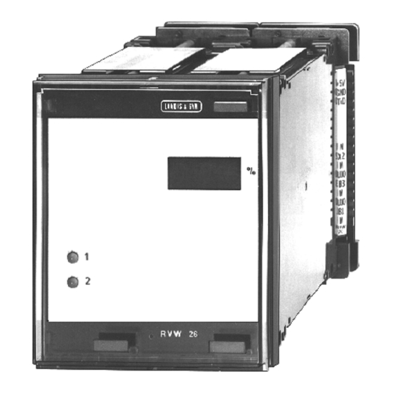
Page 6: Front View And Basic Design
Potentiometer (used with actuators) Burner control Actuator Variable speed drive Tacho-generator Load Burner output End switch «Fully closed» (used with actuators) 6/69 Siemens Building Technologies Electronic Air / Fuel Ratio Control System CC1P7873.1en HVAC Products 2 Front view and basic design 15.10.2002... -
Page 7: General
Outputs «AUX1» and «AUX2» can be used to control an additional actuating device, such as a primary air damper, an adjustable head, or a flue gas damper. 7/69 Siemens Building Technologies Electronic Air / Fuel Ratio Control System CC1P7873.1en HVAC Products 3 General 15.10.2002... -
Page 8: Application
The variable speed drive is controlled by the RVW26... as defined by the RVW25... 78731c01/0601 FUEL Fig. 3 Single-fuel burner with no auxiliary functions 8/69 Siemens Building Technologies Electronic Air / Fuel Ratio Control System CC1P7873.1en HVAC Products 3 General 15.10.2002... - Page 9 78731g01/0601 FUEL Fig. 4 Single-fuel burner with adjustable head and flue gas damper 78731g02/0601 FUEL Fig. 5 Single-fuel burner with adjustable head 9/69 Siemens Building Technologies Electronic Air / Fuel Ratio Control System CC1P7873.1en HVAC Products 3 General 15.10.2002...
- Page 10 «SA5» can also be influenced by O trim control, parameter «Disturb» on programming level 4 must be set to the same value as with the RVW25... 10/69 Siemens Building Technologies Electronic Air / Fuel Ratio Control System CC1P7873.1en HVAC Products 3 General 15.10.2002...
-
Page 11: Product Range Overview
- For use with the RVW20... of series C or higher 4 668 9846 0 - For use with the RVW25... and RVW26... 4 668 9913 0 11/69 Siemens Building Technologies Electronic Air / Fuel Ratio Control System CC1P7873.1en HVAC Products 15.10.2002... - Page 12 In that case, shutdown can occur, requiring the actuators to be replaced. 12/69 Siemens Building Technologies Electronic Air / Fuel Ratio Control System CC1P7873.1en HVAC Products 4 Product range overview 15.10.2002...
-
Page 13: Description Of Functions
The «Q2» signal for the RVW25... is generated by output «Y8» of the RVW26... The tables on the following pages show the startup and shutdown sequences. 13/69 Siemens Building Technologies Electronic Air / Fuel Ratio Control System CC1P7873.1en HVAC Products 5 Description of functions 15.10.2002... -
Page 14: Startup
The digital signals at TxD and RxD are used for optimizing the dynamic behavior of air / fuel ratio control 78731f02e/1201 14/69 Siemens Building Technologies Electronic Air / Fuel Ratio Control System CC1P7873.1en HVAC Products 5 Description of functions 15.10.2002... -
Page 15: Burner Operation
This means that the rate of load change is largely dependent on the ramp time of the variable speed drive. Should the RVW26.000B27 not be able to follow the load change of the RVW25.000B27, a stop signal will be sent to the RVW25.000B27, which stops the load change until the RVW26.000B27 delivers a go signal again. - Page 16 «MaxLoad» is the burner’s maximum output (high-fire) During normal burner operation, the current «Load» is available at terminal «X1» as a DC 0...10 V signal. 16/69 Siemens Building Technologies Electronic Air / Fuel Ratio Control System CC1P7873.1en HVAC Products 5 Description of functions...
- Page 17 During this period of time, the RVW26… makes a self-test. If successful, closes (also refer to section «Function description of power ON and reset»). 17/69 Siemens Building Technologies Electronic Air / Fuel Ratio Control System CC1P7873.1en HVAC Products 5 Description of functions...
-
Page 18: Shutdown
If this is not possible, make certain that such contacts – due to delayed signals – do not adversely affect the correct functioning of the unit 18/69 Siemens Building Technologies Electronic Air / Fuel Ratio Control System CC1P7873.1en HVAC Products 5 Description of functions 15.10.2002... -
Page 19: Function Description Of Power On And Reset
Control loop RVW26 Indication of fault 78731c03e/1001 Fig. 12 Connection of lockout reset button «EK» (example) 19/69 Siemens Building Technologies Electronic Air / Fuel Ratio Control System CC1P7873.1en HVAC Products 5 Description of functions 15.10.2002... -
Page 20: Selection Of Type Of Fuel
The type of fuel is always selected externally via terminals «F1» and «F2». For this reason, prior to setting the fuel-related parameters (curves, ignition load, etc.), the required type of fuel must first be selected externally. 20/69 Siemens Building Technologies Electronic Air / Fuel Ratio Control System CC1P7873.1en HVAC Products 5 Description of functions 15.10.2002... - Page 21 «Fully closed». AUX1(1) AUX1 AUX1(2) RVW26 RVW26 78731y01/0601 Fuel1 Fuel2 Fig. 13 Connection of the auxiliary actuators 21/69 Siemens Building Technologies Electronic Air / Fuel Ratio Control System CC1P7873.1en HVAC Products 5 Description of functions 15.10.2002...
-
Page 22: Compensation Of Hysteresis
The hysteresis can have a significant adverse effect on the combustion process. It can lead to lack of air (formation of CO and soot) or to extreme amounts of excess air (waste of energy). 22/69 Siemens Building Technologies Electronic Air / Fuel Ratio Control System CC1P7873.1en HVAC Products 5 Description of functions 15.10.2002... - Page 23 Vibrations of the actuator must be avoided since they can have an adverse effect on the combustion process, due to the mechanical play. 23/69 Siemens Building Technologies Electronic Air / Fuel Ratio Control System CC1P7873.1en HVAC Products 5 Description of functions 15.10.2002...
-
Page 24: Application Of A Correcting Variable
» 1 % » 2 % 10 % » 4 % 20 % » 5 % 30 % » 8 % 50 % 24/69 Siemens Building Technologies Electronic Air / Fuel Ratio Control System CC1P7873.1en HVAC Products 5 Description of functions 15.10.2002... - Page 25 When feeding a correcting variable signal to «X2», screened cable should be used, whereby one end of the screen must be connected to terminal «M» of the RVW25... 25/69 Siemens Building Technologies Electronic Air / Fuel Ratio Control System CC1P7873.1en...
-
Page 26: Load Signal Output "X1
5.9 Load signal output «X1» An analog signal is available at terminal «X1» of the RVW26... It corresponds to the burner output ascertained at «U1». 26/69 Siemens Building Technologies Electronic Air / Fuel Ratio Control System CC1P7873.1en HVAC Products 5 Description of functions... -
Page 27: Sequence Of Functions
Phases 8 and 9 belong to the burner's shutdown sequence (and after power ON) These phase numbers also appear on the display of the handheld terminal AZW20.20. 27/69 Siemens Building Technologies Electronic Air / Fuel Ratio Control System CC1P7873.1en HVAC Products 6 Sequence of functions 15.10.2002... -
Page 28: Sequence Diagram
= 30 s lim5 = 150 s lim8 = 30 s 28/69 Siemens Building Technologies Electronic Air / Fuel Ratio Control System CC1P7873.1en HVAC Products 6 Sequence of functions 15.10.2002... -
Page 29: Basic Diagram
Position AUX2(2) RVW25 / X1 DC 0...10 V Load AUX2 Fuel Programming select RVW25 / Q2 Control AZW20.20 Fig. 16 Basic diagram 29/69 Siemens Building Technologies Electronic Air / Fuel Ratio Control System CC1P7873.1en HVAC Products 7 Basic diagram 15.10.2002... -
Page 30: Block Circuit Diagram
Signal input «U3» DC 0...10 V for the DC 0...10 V, e.g. trim control) required speed of the speed controller of the RVW25... 30/69 Siemens Building Technologies Electronic Air / Fuel Ratio Control System CC1P7873.1en HVAC Products 8 Block circuit diagram 15.10.2002... -
Page 31: Assignment Of Terminals And Description Of Inputs / Outputs (I / O)
Extra low-voltage 78731a04/0601 RVW26... Fig. 20 Assignment of connection terminals of the ARG61.040 31/69 Siemens Building Technologies Electronic Air / Fuel Ratio Control System CC1P7873.1en HVAC Products 9 Assignment of terminals and description of inputs / outputs (I / O) 15.10.2002... -
Page 32: Description Of The Inputs / Outputs
Signal for ignition position and «CLOSE» position from the burner control +5 V DC 5 V Auxiliary voltage, max. 1 mA 32/69 Siemens Building Technologies Electronic Air / Fuel Ratio Control System CC1P7873.1en HVAC Products 9 Assignment of terminals and description of inputs / outputs (I / O) -
Page 33: Display On The Control Unit
Fuel valve closed, postpurging «FUEL1», flashes in programming -9.- Actuators close mode -XX. Fault code in the event of fault (flashing) 33/69 Siemens Building Technologies Electronic Air / Fuel Ratio Control System CC1P7873.1en HVAC Products 10 Display on the control unit 15.10.2002... -
Page 34: Handheld Terminal Azw20.20
T he ha n dh e l d te r mi na l ma y o nl y be u s e d du r i ng c om mi s s i o ni n g a n d w he n d o i ng s e r v i c e w or k . 34/69 Siemens Building Technologies Electronic Air / Fuel Ratio Control System CC1P7873.1en HVAC Products 11 Handheld terminal AZW20.20... -
Page 35: Data Storage Module Rzd20
(command «Get_Par»). When changing a parameter, that parameter will automatically be stored in both the internal data storage and the data storage module RZD20. 35/69 Siemens Building Technologies Electronic Air / Fuel Ratio Control System CC1P7873.1en HVAC Products 12 Data storage module RZD20 15.10.2002... -
Page 36: Procedure For Replacing The Rvw26
Execute command «ClrErro» on programming level 7. Measure again the end switch positions on programming level 2. The «new» unit is now ready to operate. 36/69 Siemens Building Technologies Electronic Air / Fuel Ratio Control System CC1P7873.1en HVAC Products 12 Data storage module RZD20... -
Page 37: Functional Readiness And Faults
That fault will automatically disappear when the respective parameter is changed back to within the permissible range. 37/69 Siemens Building Technologies Electronic Air / Fuel Ratio Control System CC1P7873.1en HVAC Products 13 Functional readiness and faults... -
Page 38: Error Codes And Rectification Of Faults
RVW26... and the time the fault occurred before making the reset (e.g. in the burner's Operating Manual). The following table gives a detailed description of the individual faults and contains hints on troubleshooting. 38/69 Siemens Building Technologies Electronic Air / Fuel Ratio Control System CC1P7873.1en HVAC Products 14 Error codes and rectification of faults... -
Page 39: Error Code Table With Hints On Troubleshooting
«Run». In phases 0, 8 or 9, «F1» and «Selection of fuel». «F2» are at AC 230 V. 39/69 Siemens Building Technologies Electronic Air / Fuel Ratio Control System CC1P7873.1en HVAC Products 14 Error codes and rectification of faults... - Page 40 «U1» of the RVW26... and «M» of the RVW25... broken wires of load input «U1». to «M» of the RVW26... 40/69 Siemens Building Technologies Electronic Air / Fuel Ratio Control System CC1P7873.1en HVAC Products 14 Error codes and rectification of faults...
- Page 41 Bx_0V range Bx_10V range NBx_10V range U_5V range UT_x fuel changed process timing 41/69 Siemens Building Technologies Electronic Air / Fuel Ratio Control System CC1P7873.1en HVAC Products 14 Error codes and rectification of faults 15.10.2002...
-
Page 42: Programming The Rvw26
(programming level 0) must first be made to start the burner. When the burner is running (phase «R»), a change to programming mode can be made again to optimize the settings 42/69 Siemens Building Technologies Electronic Air / Fuel Ratio Control System CC1P7873.1en HVAC Products 15 Programming the RVW26... - Page 43 The type of fuel cannot be selected with the handheld unit. This must be done exter- nally via terminals «F1» and «F2». Fig. 24 on the next page shows the display in detail. 43/69 Siemens Building Technologies Electronic Air / Fuel Ratio Control System CC1P7873.1en HVAC Products 15 Programming the RVW26...
-
Page 44: Structure Of The Display
Ignition positions Data transfer RZD20 Fault protocol RVW26... stores its data in the RZD20 Fig. 24 Display of the handheld terminal AZW20.20 44/69 Siemens Building Technologies Electronic Air / Fuel Ratio Control System CC1P7873.1en HVAC Products 15 Programming the RVW26... 15.10.2002... - Page 45 R / °: 1000 W / 135° 135° x 30 s Running time to be set = = 45 s 90° 45/69 Siemens Building Technologies Electronic Air / Fuel Ratio Control System CC1P7873.1en HVAC Products 15 Programming the RVW26... 15.10.2002...
- Page 46 Interval «INTERVA» corresponds to the time «t4» of burner controls. Setting range: 5...15 s Increment: Factory setting: LineFre Mains frequency Setting: 50 / 60 Hz Factory setting: 60 Hz 46/69 Siemens Building Technologies Electronic Air / Fuel Ratio Control System CC1P7873.1en HVAC Products 15 Programming the RVW26... 15.10.2002...
- Page 47 Settings: on / off Factory setting: Hyster Extent of compensation of hysteresis Setting range: 0.00...0.50 V Increment: 0.1 V Factory setting: 47/69 Siemens Building Technologies Electronic Air / Fuel Ratio Control System CC1P7873.1en HVAC Products 15 Programming the RVW26... 15.10.2002...
- Page 48 Position of auxiliary actuator 2 Setting range: end switch_closed + end switch_tolerance + hysteresis end switch_open – end switch_tolerance Increment: 0.04 V Factory setting: 48/69 Siemens Building Technologies Electronic Air / Fuel Ratio Control System CC1P7873.1en HVAC Products 15 Programming the RVW26... 15.10.2002...
- Page 49 The respective action is triggered by pressing button «+». When the action is completed, the display returns to «off». After lockout, the RVW26… can be reset with «ClrErro». 49/69 Siemens Building Technologies Electronic Air / Fuel Ratio Control System CC1P7873.1en HVAC Products 15 Programming the RVW26...
- Page 50 If several faults are present at the same time, they will be displayed one by one. The order of their occurrence cannot be read off. Line 3 of the display gives a brief description of the fault in English. 50/69 Siemens Building Technologies Electronic Air / Fuel Ratio Control System CC1P7873.1en HVAC Products 15 Programming the RVW26...
-
Page 51: Applications
ON or after a reset of the RVW25… and RVW26…, nonreadi- ness or a fault of the RVW25... and RVW26… will be signaled for about 2 seconds. 51/69 Siemens Building Technologies Electronic Air / Fuel Ratio Control System CC1P7873.1en... -
Page 52: Basic Diagram Of A Plant With A Modulating Burner (One Type Of Fuel)
The on / off contact of the load controller (Q13...Q14), the readiness contact of the RVW25... and RVW26… (Q4...Q5), the readiness contact of the RPO25... (Q6...Q7), and the limit thermostat. 52/69 Siemens Building Technologies Electronic Air / Fuel Ratio Control System CC1P7873.1en HVAC Products 16 Applications 15.10.2002... -
Page 53: Engineering Notes
If, for example, the gas damper has an extremely unfavorable characteristic, the po- sitioning accuracy (neutral zone) will lead to inaccuracies in terms of gas flow rate. 53/69 Siemens Building Technologies Electronic Air / Fuel Ratio Control System CC1P7873.1en HVAC Products 17 Engineering notes 15.10.2002... - Page 54 High voltage Fully open Low voltage In this case, the end switch measurement «Fully open» measures the «Fully closed» position, and vice versa. 54/69 Siemens Building Technologies Electronic Air / Fuel Ratio Control System CC1P7873.1en HVAC Products 17 Engineering notes 15.10.2002...
-
Page 55: Engineering
«M» of the RVW26... The RVW26... should be mounted such that its display is visible (error code, etc.). The actuator running times must lie between 30 and 60 seconds.. 55/69 Siemens Building Technologies Electronic Air / Fuel Ratio Control System CC1P7873.1en HVAC Products 17 Engineering notes 15.10.2002... -
Page 56: Requirements Placed On The Actuators And Potentiometers
The characteristic’s tolerance must be no more than ±1 % U [V] 10 V 78721d05/0501 50 % 100 % Fig. 37 Required linearity of the feedback potentiometer 56/69 Siemens Building Technologies Electronic Air / Fuel Ratio Control System CC1P7873.1en HVAC Products 17 Engineering notes 15.10.2002... - Page 57 If potentiometers of other manufacture are used, it is recommended to always install conductive plastic potentiometers. 57/69 Siemens Building Technologies Electronic Air / Fuel Ratio Control System CC1P7873.1en HVAC Products 17 Engineering notes...
-
Page 58: Requirements Placed On The Variable Speed Drive And The Fan Speed Feedback Signal
To provide control, the variable speed drive must have the following inputs: · Analog input DC 0...10 V · Start / stop 58/69 Siemens Building Technologies Electronic Air / Fuel Ratio Control System CC1P7873.1en HVAC Products 17 Engineering notes 15.10.2002... -
Page 59: Notes On The Commissioning Of A Burner
On programming level 5, set the 5 curvepoints for all actuators. This is the ba- sic setting used to enable burner startup. The fine-tuning will be made later when the burner is running, including measurement of the emissions 59/69 Siemens Building Technologies Electronic Air / Fuel Ratio Control System CC1P7873.1en HVAC Products 18 Notes on the commissioning of a burner 15.10.2002... - Page 60 «Disturb» factor such that the RVW25... and RVW26… will be able to compensate all effects (supply air temperature, calorific value, etc.). 60/69 Siemens Building Technologies Electronic Air / Fuel Ratio Control System CC1P7873.1en HVAC Products 18 Notes on the commissioning of a burner 15.10.2002...
-
Page 61: Setting Instructions For The Rvw26
Repeat step 4 until all programmable curvepoints are adjusted down to the low-fire position values. Interpolate the curvepoints below the low-fire position value (e.g. 0 %). 61/69 Siemens Building Technologies Electronic Air / Fuel Ratio Control System CC1P7873.1en HVAC Products 18 Notes on the commissioning of a burner 15.10.2002... - Page 62 Pnew Required load value after fuel reduction Pold Current load value before fuel reduction 62/69 Siemens Building Technologies Electronic Air / Fuel Ratio Control System CC1P7873.1en HVAC Products 18 Notes on the commissioning of a burner 15.10.2002...
-
Page 63: Permissible Range Of Curvepoints
Maximum burner output Disturb x MinLoad 100 % MinLoad MaxLoad Load [%] IgnitLo Fig. 30 Permissible range of curvepoints 63/69 Siemens Building Technologies Electronic Air / Fuel Ratio Control System CC1P7873.1en HVAC Products 18 Notes on the commissioning of a burner 15.10.2002... -
Page 64: Setting Report
Impact of correcting variable on actuator Aux2Dis..... (on ........(on (AUX2) off) off) Settings also apply to fuel 2 64/69 Siemens Building Technologies Electronic Air / Fuel Ratio Control System CC1P7873.1en HVAC Products 18 Notes on the commissioning of a burner 15.10.2002... - Page 65 Position of auxiliary actuator 1 on ignition Aux1Pos ......[V] Position of auxiliary actuator 2 on ignition Aux2Pos ......[V] 65/69 Siemens Building Technologies Electronic Air / Fuel Ratio Control System CC1P7873.1en HVAC Products 18 Notes on the commissioning of a burner...
- Page 66 78731t01/0601 66/69 Siemens Building Technologies Electronic Air / Fuel Ratio Control System CC1P7873.1en HVAC Products 18 Notes on the commissioning of a burner 15.10.2002...
- Page 67 78731t02e/1002 67/69 Siemens Building Technologies Electronic Air / Fuel Ratio Control System CC1P7873.1en HVAC Products 18 Notes on the commissioning of a burner 15.10.2002...
-
Page 68: Technical Data
(refer to «Product range overview») Actuator running times 30...60 s (the various actuators may have different running times, refer to «Product range overview») 68/69 Siemens Building Technologies Electronic Air / Fuel Ratio Control System CC1P7873.1en HVAC Products 19 Technical data 15.10.2002... - Page 69 0...+60 °C Humidity < 95 % r.h. Condensation, formation of ice and ingress of water are not permitted! Siemens Building Technologies © 2002 Siemens Building Technologies Landis & Staefa Produktion GmbH Subject to change! Berliner Ring 23 D-76437 Rastatt Tel. +49 7222 598 0 Fax +49 7222 598 269 www.landisstaefa.com...
Need help?
Do you have a question about the RVW26.000B27 and is the answer not in the manual?
Questions and answers